Universal Flash Storage (UFS) 4.1 is the latest iteration of the JEDEC standard for high-performance, low-power embedded flash storage, primarily targeted at smartphones, tablets, automotive systems, IoT devices, and edge AI applications. JEDEC officially published the UFS 4.1 specification (JESD220G) and the complementary UFS Host Controller Interface (UFSHCI) 4.1 (JESD223F) on January 8, 2025.
UFS serves as a serial interface replacing slower eMMC storage in mobile devices, offering significantly higher speeds, better power efficiency, and advanced features while maintaining a compact BGA package (typically 9mm × 13mm or similar variants for automotive).
Key Technical Specifications and Improvements
UFS 4.1 builds directly on UFS 4.0 (released 2022) with hardware compatibility—meaning devices supporting UFS 4.0 can often use UFS 4.1 modules without major redesigns. It leverages MIPI M-PHY 5.0 (High-Speed Gear 5) and UniPro 2.0, enabling a theoretical interface bandwidth of up to 23.2 Gbps per lane (or ~46.4 Gbps per device with two lanes), translating to real-world sequential performance approaching ~4.2 GB/s for both reads and writes.
Major enhancements in UFS 4.1 over UFS 4.0 include:
- Zoned Storage for UFS — Groups similar data into zones for improved read/write efficiency and reduced fragmentation, especially beneficial for AI workloads and sustained performance.
- Host-initiated defragmentation — Allows the host to trigger internal cleanup, boosting long-term read speeds (up to 60% in some implementations) and maintaining performance over time.
- WriteBooster extensions — Features like WriteBooster Buffer Resizing, Pinned Partial Flush Modes, and improved SLC caching for faster sequential writes, quicker app installs, video recording, and gaming.
- Device-level improvements — Better exception event handling, device health notifications, enhanced boot LUN protection, and partial flush options for optimized power and throughput.
- Power and efficiency gains — Further reductions in energy consumption compared to UFS 4.0/3.1, critical for battery-powered devices and thermal management in slim phones or automotive environments.
- Security and reliability — Enhanced features for data integrity, cybersecurity (relevant for automotive), and support for advanced standards like ASIL-B and ASPICE in vehicle applications.
Performance context vs. prior generations (approximate real-world peaks; actual results vary by controller, NAND type, capacity, and workload):
- UFS 3.1 (2020): ~2,100 MB/s read, ~1,200 MB/s write.
- UFS 4.0 (2022): Roughly doubles to ~4,200 MB/s read, ~2,800 MB/s write; ~46% better power efficiency than 3.1.
- UFS 4.1 (2025): Maintains or slightly exceeds 4.0 peak bandwidth while adding efficiency, random I/O, and sustained performance via zoning/defragmentation. Some implementations (e.g., with advanced NAND) show 15–40% gains in random reads/writes or 25%+ in sequential writes.
Manufacturers like SK hynix report best-in-class sequential reads and lower power with their 321-layer TLC 4D NAND UFS 4.1 solutions, optimized for on-device AI.
NAND Technology and Variants
UFS 4.1 devices integrate a controller with advanced 3D NAND:
- TLC (Triple-Level Cell): Common for balanced performance/endurance in flagship phones (e.g., SK hynix 321-layer, Micron G9, Samsung, KIOXIA BiCS FLASH 8th-gen).
- QLC (Quad-Level Cell): Higher density for cost-effective high-capacity storage (up to 1TB+), read-intensive use cases. KIOXIA sampled QLC UFS 4.1 in early 2026 with up to 25% faster sequential writes, 90% faster random reads, and 95% faster random writes vs. prior QLC UFS 4.0, plus reduced write amplification (up to 3.5× improvement).
Capacities typically range from 128GB to 1TB (or higher in future), in compact packages suitable for foldables and slim designs. Automotive versions add ruggedization (AEC-Q100/104 Grade 2, up to 115°C operation) and safety certifications.
Real-World Benefits and Use Cases
- Smartphones & Mobile: Faster app launches, multitasking, game loading, 8K video handling, and large file transfers. On-device AI (e.g., generative models, photo editing) benefits from low-latency access and zoning for multiple models without excessive memory needs.
- Automotive: Supports ADAS, AI cockpits, infotainment, sensor data logging (cameras, LiDAR), and over-the-air updates. Micron and KIOXIA emphasize doubled bandwidth for intelligent vehicles.
- Other: Tablets, IoT, edge computing—where power, size, and sustained performance matter.
Nuances and edge cases:
- Actual speeds depend on the host controller (SoC support for Gear 5), thermal throttling, workload (sequential vs. random), and firmware. Many devices advertise UFS 4.0/4.1 but deliver lower sustained figures in benchmarks.
- UFS 4.1 is often not a dramatic day-to-day upgrade over well-implemented UFS 4.0 for casual users (e.g., some flagship phones like certain Galaxy S26 variants stuck with 4.0 showed minimal perceptible difference). Heavy users (gamers, content creators, AI enthusiasts) notice gains in install times, sustained writes, and longevity.
- Backward compatibility ensures smooth transitions, but full benefits require UFS 4.1-compliant hosts.
- Power savings accumulate over time, improving battery life in high-usage scenarios.
- Longevity: Features like better defragmentation and WriteBooster management help mitigate NAND wear, though QLC variants trade some endurance for capacity.
Industry Adoption (as of early 2026)
Major players have rolled out or sampled UFS 4.1:
- SK hynix: 321-layer TLC for mobile AI optimization; began supplying related solutions in 2025.
- Micron: G9 NAND-based, including automotive variants with strong AI and safety focus; shipping qualification samples by late 2025.
- KIOXIA: TLC and QLC variants (8th-gen BiCS with CBA technology); automotive and mobile sampling, emphasizing efficiency and high capacity.
- Samsung: UFS 4.1 for mobile and automotive, up to 1TB, with efficiency gains for AI phones and foldables.
Early adoption appeared in high-end devices (e.g., some Xiaomi models) and automotive platforms. UFS 5.0 was already in development by early 2026, promising further doublings in performance.
Implications and Future Considerations
UFS 4.1 accelerates the shift toward AI-centric devices by enabling faster data movement with lower power—key as on-device processing grows to reduce cloud dependency and latency. In automotive, it supports safer, more responsive systems amid increasing sensor data volumes.
Challenges include thermal management in dense packages, ensuring SoC compatibility for peak speeds, and balancing cost (QLC vs. TLC). For consumers, checking device specs matters less than overall system optimization; for OEMs and developers, the new features (zoning, defrag) require software support to maximize value.
In summary, UFS 4.1 refines an already fast standard with targeted optimizations for efficiency, sustained performance, and AI/automotive demands, while preserving compatibility. It represents an evolutionary step that will underpin flagship mobile and intelligent vehicle storage through the late 2020s, with real benefits most evident in demanding, data-intensive workloads.
A) Universal Flash Storage protocol stack
Typical UFS Stack (Universal Flash Storage protocol stack) is a modular, layered communication architecture optimized for high-performance, low-power embedded storage. It is defined in the JEDEC UFS specifications (e.g., JESD220G for UFS 4.1) and leverages standards from the MIPI Alliance for the lower layers. The stack enables efficient bursty data transfers between a host (typically an application processor/SoC) and a UFS device (controller + NAND flash) while supporting advanced features such as command queuing, power management, and intelligent host-device collaboration.
The architecture follows a simplified OSI-like model with three primary layers, ensuring clear separation of concerns: command semantics at the top, reliable transport in the middle, and high-speed serial interconnect at the bottom. This design is symmetric between host and device sides but with different implementations— the host focuses on queuing and issuance (via UFSHCI), while the device emphasizes media management and feature execution (via its internal FTL and firmware).
High-Level View of the Typical UFS Stack
UFS communication is structured as follows (top to bottom):
- UFS Application / Command Layer (UCS – UFS Command Set)
- Based on the SCSI Architectural Model (SAM-5).
- Includes the UFS Command Set (subset of SCSI commands for read/write, inquiry, etc.), Task Manager (for task abort/clear/priority), and Device Manager (for attributes, flags, power modes, exceptions, and descriptors).
- This layer interfaces with host software (e.g., OS SCSI mid-layer in Android/Linux) or device firmware.
- In UFS 4.1, it exposes new capabilities such as host-initiated defragmentation, Zoned Storage (ZUFS) management, WriteBooster resize/pin/partial flush commands, enhanced exception handling, and RPMB security flows.
- UFS Transport Protocol (UTP) Layer
- Encapsulates SCSI commands, data, and responses into UFS Protocol Information Units (UPIUs) — Command UPIU, Data UPIU, Response UPIU, Task Management UPIU, etc.
- Handles segmentation/reassembly, basic flow control, and error detection at the transport level.
- Provides a clean abstraction between the command layer and the interconnect. UPIUs are exchanged between host and device UTP peers.
- UFS Interconnect Layer (UIC – UFS InterConnect)
- The high-speed serial link between host and device.
- Composed of two MIPI specifications:
- MIPI UniPro v2.0 (Transport and Link Layers): A packet-based protocol with four layers plus Device Management Entity (DME):
- Layer 4 (Transport, T): Connection-oriented, up to 2047 CPorts (virtual channels), end-to-end flow control.
- Layer 3 (Network, N): Addressing and routing.
- Layer 2 (Data Link, DL): Reliable delivery with CRC, retransmission, windowed acknowledgments, credit-based flow control, and traffic class preemption.
- Layer 1.5 (PHY Adapter, PA): Abstracts the physical layer, manages lanes, power states, and link initialization.
- DME: Centralized management for attributes and power.
- Key optimizations in v2.0: Larger packet payloads (1144 bytes), reduced link startup latency, and streamlined low-speed modes for storage workloads.
- MIPI M-PHY v5.0 (Physical Layer): Serial differential signaling with embedded clocking.
- High-Speed Gear 5 (HS-G5): Up to 23.32 Gbps per lane (Rate B; Rate A for EMI optimization).
- Typical dual-lane (x2) configuration: ~46.64 Gbps raw aggregate → ~4.2–4.3 GB/s effective sequential throughput after 8b/10b encoding (~20% overhead) and protocol overhead.
- Signaling: NRZ with 8b/10b encoding for DC balance and clock recovery.
- Power states: Active HS bursts, STALL, SLEEP, and deep HIBERN8 (ultra-low power, ~30 µW in optimized IP).
- Additional features: Adaptive equalization, amplitude options (Large/Small), slew-rate control, and dithering for low EMI in compact mobile/automotive designs.
- MIPI UniPro v2.0 (Transport and Link Layers): A packet-based protocol with four layers plus Device Management Entity (DME):
The UIC provides two service access points to the upper layers:
- UIC_SAP: For transporting UPIUs between host and device.
- UIO_SAP: For issuing commands to UniPro layers (e.g., link startup, power mode changes, attribute configuration).
Host vs. Device Implementation Differences
- Host Side: Implemented via UFSHCI 4.1 (JESD223F) — register interface, command queuing (including Multi-Circular Queue/MCQ for prioritization), DMA engines (PRDT scatter-gather), interrupt handling, and power coordination. The common driver (e.g., Linux UFSHCD) interacts with this layer. New UFS 4.1 support includes mechanisms for host-initiated defragmentation, WriteBooster controls, and granular exceptions.
- Device Side: Handled by the UFS Device Controller (integrated with NAND). It includes a full Flash Translation Layer (FTL) for mapping, wear leveling, bad block management, and ECC. Firmware executes intelligent features (zoning, defragmentation logic, pinned WriteBooster buffering) and coordinates background operations (GC, refresh) more efficiently due to host collaboration. Security (RPMB) and boot LUN protection are also managed here.
Key Characteristics of the Typical UFS Stack
- Bursty and Power-Optimized: Designed for short high-bandwidth transfers followed by long idle periods. Rapid transitions to HIBERN8 and features like zoning/defragmentation/pinned flushing reduce unnecessary activity.
- Full-Duplex and Scalable: Typically 2 lanes (TX + RX pairs), supporting asymmetric workloads (e.g., heavy reads during AI model loading).
- Reliability and Error Handling: CRC/retransmission in UniPro DL, enhanced exceptions and health telemetry in UFS 4.1, plus robust NAND management.
- Security Integration: RPMB authentication flows, secure erase, and boot protection traverse the stack.
- Backward Compatibility: UFS 4.1 stack negotiates with earlier versions, falling back gracefully while preserving full HS-G5 benefits when both sides support it.
Visual Representation (Typical UFS Stack Diagram)
Here is the standard layered view (same for both host and device, with implementation differences noted):
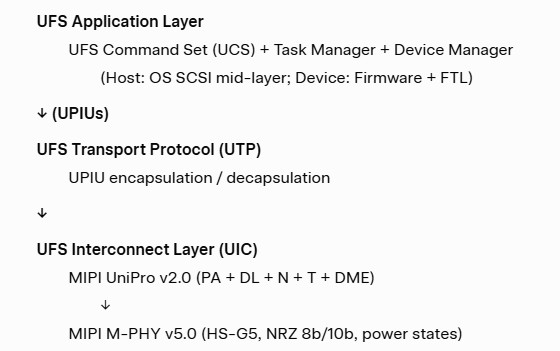
This stack connects the host controller (via UFSHCI) to the device controller over differential lanes in a compact BGA package.
Implications for UFS 4.1
The layered design allows host-device collaboration without tight coupling. The upper layers (UCS/UTP) carry new UFS 4.1 commands for intelligent maintenance, while the interconnect (UniPro + M-PHY) provides the high-speed, low-power foundation (~4.2–4.3 GB/s effective). This results in better sustained performance, lower energy per bit, improved endurance (via reduced WAF), and enhanced reliability/security compared to earlier generations.
In mobile/flagship smartphones and automotive systems, the stack enables fast app/AI loading, smooth multitasking, reliable sensor logging, and efficient power management. Actual delivered performance depends on firmware quality, NAND type (TLC vs. QLC), host driver support, thermal design, and workload.
B) UFS 4.1 Layered Architecture: Host Side
UFS 4.1 Layered Architecture: Host Side focuses on the host-side components that initiate, manage, and optimize communication with the UFS device. While the overall UFS protocol stack is symmetric in concept (host and device), the host side is implemented through the UFS Host Controller Interface (UFSHCI) 4.1 (JEDEC JESD223F, published alongside JESD220G in January 2025). This specification provides a standardized hardware/software interface, enabling a common driver to work across different SoC vendors while fully exposing UFS 4.1 device capabilities.
The host-side architecture is designed for high-performance, low-power, burst-oriented storage workloads in smartphones, automotive domain controllers, and edge AI devices. It abstracts complexity, supports multi-queue prioritization, and adds explicit controls for new 4.1 features such as host-initiated defragmentation, WriteBooster buffer resizing/pinned partial flush, and enhanced exception handling.
Overall UFS Protocol Stack Context (Host Perspective)
UFS uses a layered model based on the SCSI Architectural Model (SAM):
- Application/Command Layer (UFS Command Set – UCS)
- Transport Layer – UFS Transport Protocol (UTP)
- Interconnect Layer (UIC) – MIPI UniPro v2.0 + MIPI M-PHY v5.0 (HS-G5)
On the host side, these layers are realized through:
- System software / OS SCSI mid-layer
- UFS Host Controller Driver (UFSHCD)
- UFS Host Controller hardware (implemented via UFSHCI 4.1 registers and logic)
- MIPI UniPro + M-PHY IP blocks
The UFSHCI 4.1 defines the register interface, data structures, queuing model, and command flows that connect host software to the lower interconnect layers.
Detailed Host-Side Layers and Components
1. Application / SCSI Command Layer (Host Software Side)
- The host OS (e.g., Android/Linux SCSI framework or automotive RTOS) issues SCSI commands (READ(10), WRITE(10), etc.) via the standard SCSI mid-layer.
- UFS Command Set (UCS) handles storage-specific commands, task management, and device management.
- UFS 4.1 Extensions Exposed Here:
- Host-initiated defragmentation commands/attributes for triggering internal device data relocation.
- WriteBooster control: buffer resize requests, data pinning (via specific GROUP NUMBER in WRITE commands), and partial flush modes.
- Zoned Storage (ZUFS) management commands for zone-aware operations.
- Enhanced device health queries and exception handling.
- This layer benefits from UFSHCI’s queuing and prioritization to maintain high random I/O and low latency for app launches, AI inference, and multitasking.
2. UFS Transport Protocol (UTP) Layer (Handled by UFSHCI)
- Encapsulates SCSI commands, data, and responses into UFS Protocol Information Units (UPIUs): Command UPIU, Data UPIU, Response UPIU, Task Management UPIU, etc.
- Manages segmentation, flow control, and basic error detection at the transport level.
- In UFSHCI 4.1, the host controller hardware implements UTP queues and DMA engines for efficient data movement between system memory and the interconnect.
- Key structures:
- UTP Transfer Request List (TRL): List of outstanding transfer requests.
- Command Descriptor and Physical Region Descriptor Table (PRDT): Support for scatter-gather lists; UFSHCI 4.1 includes 2DW PRDT extensions for efficiency.
3. UFS Host Controller Interface (UFSHCI 4.1) – The Core Host-Side Hardware Abstraction
- Purpose: Provides a uniform register-based interface so a single common driver can control any compliant UFS host controller hardware.
- Main Functional Blocks (typical conceptual diagram from JEDEC and IP vendors like Arasan, Synopsys, M31):
- Register Interface: Memory-mapped registers for configuration, status, interrupts, and command submission.
- Command Queuing Engine:
- Legacy doorbell-based queuing (up to 32 doorbells).
- Multi-Circular Queue (MCQ) support (enhanced in 4.x) for better prioritization and scalability in multi-core or mixed workloads.
- DMA Engine: Handles data transfer between host system memory and the UIC (UniPro/M-PHY) using PRDTs.
- UIC Command Interface: Registers for issuing commands to UniPro layers (e.g., link startup, power mode changes, attribute configuration).
- Interrupt and Event Handler: Efficient notification of command completions, errors, device exceptions, and health events.
- Power Management Logic: Coordinates host-side power state transitions with device and M-PHY states (HIBERN8, STALL, etc.).
- UFSHCI 4.1-Specific Refinements:
- Explicit support for new UFS 4.1 commands/attributes related to host-initiated defragmentation, WriteBooster resizing, pinned/partial flush, and granular exceptions.
- Improved exception reporting and device health telemetry handling.
- Better integration with security features (RPMB authentication for vendor commands, boot LUN protection).
4. UFS Interconnect Layer (UIC) – Host-Side Implementation
- MIPI UniPro v2.0 Controller IP: Implements PA, DL, N, T layers + DME on the host. Manages reliable packet transport, credit-based flow control, larger payloads (1144 bytes), and fast link startup.
- MIPI M-PHY v5.0 IP: Physical layer handling differential NRZ signaling, 8b/10b encoding, HS-G5 (up to 23.32 Gbps/lane), adaptive equalization, and power states.
- Communication between UFSHCI and UniPro/M-PHY typically uses a standardized interface (e.g., RMMI for M-PHY).
Host-Side Data Flow Example
- Host software submits a SCSI command (via UFSHCD).
- UFSHCI enqueues it in the appropriate queue (MCQ or legacy), builds UPIU, and triggers DMA.
- UTP layer encapsulates → UniPro packetizes → M-PHY serializes and transmits over the lanes.
- Device processes and responds; completion flows back through the same layers to generate an interrupt.
- For 4.1 features: Host software issues specific commands (e.g., defragmentation trigger or WriteBooster resize) that UFSHCI translates and forwards.
Nuances, Edge Cases, and Implementation Considerations
- Software Stack Dependency: Linux UFSHCD (ufshcd.c) or equivalent in Android/automotive OS must be updated to support UFS 4.1 commands. Without updates, new features are unavailable or limited.
- Queuing Advantages: MCQ and prioritization reduce latency in multitasking or AI workloads (e.g., foreground user I/O vs. background sync).
- Power and Thermal: UFSHCI coordinates rapid power state transitions; host-initiated maintenance (defrag, smart flushing) reduces background activity, improving HIBERN8 residency and energy per bit.
- Automotive Variants: Enhanced exception handling, telemetry, and safety mechanisms (ASIL-B support in some IP) ensure reliable operation under extended temperatures and high-duty cycles.
- IP Integration: Commercial UFS Host Controller IP (Arasan, Synopsys, M31) includes full UFSHCI 4.1 compliance, UniPro v2.0, M-PHY v5.0, inline encryption, and MCQ. Typically connected via AXI/ACE to the SoC bus.
- Backward Compatibility: UFSHCI 4.1 works seamlessly with UFS 4.0/earlier devices; new registers and commands are additive.
- Testing/Validation: MIPI CTS for UniPro/M-PHY + JEDEC compliance suites for UFSHCI flows. Real performance depends on host tuning, thermal design, and driver quality.
- Edge Cases: High-capacity QLC benefits from host-controlled maintenance to manage WAF; slim mobile devices gain from reduced background interference.
Implications for UFS 4.1 Systems
The host-side architecture in UFS 4.1 makes the interface truly collaborative. The host gains fine-grained control over device maintenance (defragmentation, zoning, WriteBooster), leading to better sustained performance, lower power, improved random I/O, and longer NAND endurance—critical for on-device AI and automotive applications. Without a capable UFSHCI 4.1 implementation and updated driver, many 4.1 benefits remain underutilized.
In summary, the UFS 4.1 host-side layered architecture centers on UFSHCI 4.1 (JESD223F) as the standardized hardware abstraction layer. It bridges the SCSI application layer and UTP with the MIPI UniPro v2.0 + M-PHY v5.0 interconnect, while adding explicit support for intelligent host-orchestrated features. This design ensures a common driver model, high efficiency, and full exploitation of UFS 4.1’s evolutionary improvements (zoning, defragmentation, advanced WriteBooster, enhanced exceptions).
C) UFS 4.1 Layered Architecture: Device Side
UFS 4.1 Layered Architecture: Device Side mirrors the overall UFS protocol stack but shifts focus to the storage device’s responsibilities: processing incoming commands, managing NAND flash media, executing background operations, and responding efficiently while implementing intelligent features like Zoned Storage (ZUFS), host-initiated defragmentation, and advanced WriteBooster controls. JEDEC JESD220G (UFS 4.1) defines the device behavior, with the interconnect layers shared symmetrically with the host.
The device side is more complex than the host side because it includes not only protocol handling but also a full Flash Translation Layer (FTL), NAND management, and firmware that executes the collaborative optimizations introduced in UFS 4.1. The architecture follows the same SCSI-based model as the host, ensuring interoperability.
Overall UFS Protocol Stack (Device Perspective)
UFS uses a layered architecture based on the SCSI Architectural Model (SAM):
- Application / Command Layer (Device Manager + UFS Command Set execution)
- UFS Transport Protocol (UTP) Layer
- UFS Interconnect Layer (UIC): MIPI UniPro v2.0 (link/transport) + MIPI M-PHY v5.0 (physical)
On the device side, these layers are implemented in the UFS Device Controller (a dedicated SoC-like chip inside the UFS package), which sits between the interconnect and the raw NAND flash array (typically advanced 3D TLC or QLC dies, e.g., SK hynix 321-layer 4D NAND or KIOXIA 8th-gen BiCS with CBA technology).
Detailed Device-Side Layers and Components
1. Application / Command Layer (Device Firmware / Device Manager)
- Processes incoming SCSI commands from the host (via UTP-decapsulated UPIUs).
- Includes:
- UFS Command Set (UCS) Execution: Handles READ(10), WRITE(10), INQUIRY, MODE SELECT/SENSE, etc., with support for tagged command queuing.
- Task Manager: Manages task abort, clear, and priority.
- Device Manager: Maintains descriptors, attributes, flags, power modes, and exception events. It responds to host queries for health, configuration, and new 4.1 features.
- UFS 4.1-Specific Intelligence (implemented here):
- Zoned Storage (ZUFS): Manages zone-based data placement, sequential write encouragement within zones, zone reset, and reporting. Reduces FTL mapping overhead and write amplification.
- Host-Initiated Defragmentation: Receives and executes host-triggered data relocation commands. Optimizes physical layout for better read paths and defers garbage collection (GC).
- WriteBooster Extensions: Implements pseudo-SLC (pSLC) buffer management, including dynamic buffer resizing (per host request), data pinning (hot data stays in fast SLC), and partial flush operations. Pinned data enables low-latency random reads without main TLC/QLC access.
- Enhanced Exception Handling: Generates granular exceptions for LUN-specific issues (e.g., wear thresholds, integrity problems) and supports richer vendor-specific health notifications/telemetry for predictive maintenance.
- Security Features: Processes RPMB (Replay Protected Memory Block) authentication, secure erase/purge, and boot LUN protection. Includes permanent bootable LUN configuration.
- This layer works closely with the internal Flash Translation Layer (FTL) to map logical addresses to physical NAND pages/blocks, perform wear leveling, bad block management, and error correction.
2. UFS Transport Protocol (UTP) Layer (Device Controller)
- Decapsulates incoming UPIUs from the interconnect layer and generates response UPIUs.
- Handles data transfer (in/out), task management, and basic flow control.
- Prepares data for the command layer or forwards it to the FTL/NAND.
- In UFS 4.1, supports efficient handling of new command types (e.g., defragmentation triggers, WriteBooster controls) with minimal overhead.
3. UFS Interconnect Layer (UIC) – Device-Side Implementation
- MIPI UniPro v2.0 Controller (on-device IP):
- Implements the four layers (PA, DL, N, T) + Device Management Entity (DME).
- Manages reliable packet delivery, credit-based flow control, larger payloads (1144 bytes for efficiency), and fast link startup.
- Coordinates power state transitions (e.g., entry/exit from HIBERN8) with the host.
- MIPI M-PHY v5.0 (physical layer IP):
- Serial differential NRZ signaling with 8b/10b encoding (~20% overhead).
- Supports High-Speed Gear 5 (HS-G5): up to 23.32 Gbps per lane (Rate B). Dual-lane configuration yields ~46.64 Gbps raw aggregate → ~4.2–4.3 GB/s effective sequential throughput.
- Power states: Active HS bursts, STALL, SLEEP, and ultra-low HIBERN8 (~30 µW in optimized implementations).
- Features adaptive equalization, amplitude control, slew-rate management, and short-channel optimization suitable for compact BGA packages (typically 9×13 mm, as thin as 0.85 mm in advanced NAND implementations).
The interconnect provides two service access points:
- UIC_SAP: For transporting UPIUs between host and device.
- UIO_SAP: For issuing commands to UniPro layers (e.g., power mode changes, attribute configuration).
Device-Side Block Diagram (Conceptual)
A typical UFS 4.1 device contains:
- UFS Device Controller (SoC-like chip): Implements UTP, UniPro, M-PHY interface, FTL, command processing, and feature logic (zoning, defrag, WriteBooster).
- NAND Flash Array: Multiple stacked 3D dies (TLC for balanced endurance/performance; QLC for high capacity/read-intensive use). Includes internal ECC, wear leveling, and over-provisioning.
- Power Management: Voltage regulators for core, I/O, and NAND (VCC, VCCQ, VCCQ2).
- Boot and Security Partitions: Dedicated boot LUNs with enhanced protection and RPMB for sensitive data.
Data flow (incoming): Host → M-PHY (serial) → UniPro (packet processing) → UTP (UPIU decapsulation) → Command Layer / FTL → NAND access (with possible WriteBooster buffering or zone management).
Outgoing responses follow the reverse path.
Key Device-Side Characteristics in UFS 4.1
- Intelligent FTL and Background Operations: Firmware executes GC, wear leveling, and refresh more efficiently thanks to host collaboration. Host-initiated defragmentation and zoning reduce autonomous GC frequency and intensity, lowering WAF and improving endurance/long-term read performance.
- Power Efficiency: Device coordinates rapid power state transitions. Features like pinned partial WriteBooster flushes and zoning minimize unnecessary NAND activity, enabling longer HIBERN8 residency and lower energy per bit (incremental gains over UFS 4.0, e.g., 7% in some SK hynix 321-layer implementations).
- Reliability Mechanisms: Granular exception handling, health telemetry (vendor-specific descriptors), and predictive maintenance support. Automotive variants add AEC-Q100/104, ASIL-B functional safety, and extended temperature operation (up to 115°C).
- Security: RPMB with enhanced authentication (including for vendor commands), larger transfer sizes (up to 4 KB), and targeted purge. Boot LUN protection and permanent bootable configurations.
- Performance Optimizations: The device executes host requests for WriteBooster resizing/pinning and zone management, delivering sustained random I/O gains (e.g., +15–95% in vendor-tuned TLC/QLC implementations) and better consistency as storage fills.
Nuances, Edge Cases, and Implementation Considerations
- Firmware Complexity: The device controller firmware is responsible for implementing all UFS 4.1 intelligence (ZUFS, defragmentation logic, WriteBooster pinning). Quality of firmware significantly affects real-world sustained performance, power, and endurance.
- Host Dependency: Many advanced reliability and efficiency features (defagmentation triggers, zoning commands, pinning) are host-initiated. Without updated host drivers (via UFSHCI 4.1), the device falls back to more autonomous (and potentially less optimal) behavior similar to UFS 4.0.
- NAND Variations: TLC implementations (e.g., SK hynix 321-layer) prioritize balanced performance/endurance with AI optimizations. QLC variants (e.g., KIOXIA) leverage 4.1 features to mitigate higher WAF, enabling cost-effective high-capacity (512 GB–1 TB+) solutions.
- Automotive Edge Cases: Continuous high-duty-cycle logging benefits from zoned append-only patterns and delayed GC; enhanced diagnostics and telemetry support predictive maintenance under thermal/vibration stress.
- Package and Integration: Compact BGA (9×13 mm typical, 0.85 mm thin in advanced designs) integrates controller + NAND dies. Power domains (core, I/O, NAND) are carefully managed for low leakage.
- Testing and Validation: MIPI conformance suites validate UniPro/M-PHY on the device side; JEDEC compliance covers UFS command flows, exceptions, and new 4.1 features. Real performance depends on controller firmware tuning, NAND quality, and thermal design.
- Backward Compatibility: UFS 4.1 devices work in UFS 4.0 hosts (with reduced feature set). The interconnect layers ensure seamless link negotiation.
Implications for UFS 4.1 Systems
On the device side, the layered architecture enables intelligent, collaborative storage. The device not only responds to basic read/write commands but actively participates in optimization through features like zoning (reduced fragmentation), host-triggered defragmentation (sustained reads), and smart WriteBooster management (faster random access with lower WAF). This results in better long-term performance, lower power, improved endurance, and higher reliability—critical for on-device AI (efficient multi-model handling), flagship smartphones (smooth multitasking as storage fills), and automotive systems (reliable sensor logging and safety-critical operation).
In contrast to the host side (which focuses on queuing, DMA, and command issuance via UFSHCI), the device side emphasizes media management, feature execution, and responsive intelligence.
In summary, the UFS 4.1 device-side layered architecture consists of the Application/Command Layer (with rich 4.1 feature logic and FTL), UTP Layer, and Interconnect Layer (UniPro v2.0 + M-PHY v5.0 HS-G5). The integrated UFS Device Controller orchestrates NAND access while implementing host-collaborative optimizations for zoning, defragmentation, WriteBooster extensions, exceptions, and security. This design makes UFS 4.1 more resilient and efficient than prior generations, particularly in sustained or fragmented workloads.
1) Universal Flash Storage 4.1: Technical Specifications
Universal Flash Storage (UFS) 4.1 is defined by the JEDEC JESD220G specification (published December 2024/January 2025) and the complementary UFS Host Controller Interface (UFSHCI) 4.1 in JESD223F. It refines UFS 4.0 (2022) with targeted optimizations for sustained performance, power efficiency, and emerging workloads like on-device AI, while preserving full hardware compatibility with UFS 4.0 implementations.
UFS 4.1 targets high-performance, low-power embedded storage in smartphones, tablets, automotive systems (ADAS, infotainment, domain controllers), edge AI devices, and other compact computing platforms. It uses a serial interface based on MIPI M-PHY and UniPro protocols, replacing slower parallel interfaces like eMMC with significantly higher bandwidth, better queuing, and advanced power management.
Interface and Physical Layer Specifications
UFS 4.1 builds on the same foundational physical and link layers as UFS 4.0:
- MIPI M-PHY v5.0 with High-Speed Gear 5 (HS-G5): Supports up to 23.32 Gbps per lane (Rate A/B variants for balancing EMI and throughput). With the typical dual-lane configuration (x2), this yields a theoretical aggregate bandwidth of approximately 46.64 Gbps.
- MIPI UniPro v2.0: Handles the transport and network layers, enabling efficient packet-based communication with low overhead.
- Effective real-world sequential throughput: Up to ~4.2–4.3 GB/s for both reads and writes (depending on implementation, controller, NAND type, and workload). Some vendors report peaks of 4.3 GB/s sequential read with advanced NAND.
- Signaling and encoding: Differential signaling in HS mode with 8b/10b encoding (introducing ~20% overhead), plus support for lower gears (HS-G1 to HS-G4 mandatory or optional as per prior specs) and PWM low-speed modes for initialization and power saving.
- Power states: Includes Hibernate (HIBERN8), Sleep, Stall, and deep low-power modes. UFS 4.1 refines power gating and exception handling for further efficiency gains over UFS 4.0 (which already offered ~46% better efficiency than UFS 3.1 in some metrics).
Backward compatibility: UFS 4.1 devices work in UFS 4.0 hosts (and often earlier with reduced features). Full benefits require a compliant host controller supporting Gear 5 and new command extensions.
Package: Standard BGA (typically 9 × 13 mm, 153-ball or similar) for mobile; automotive variants add thermal ruggedization (AEC-Q100/104 Grade 2, up to 115°C case temperature). Thickness can be as low as 0.85 mm in advanced implementations.
Performance Characteristics
Performance varies by vendor, NAND technology (TLC vs. QLC), capacity, firmware, thermal conditions, and host optimization. Approximate peaks (real-world benchmarks often lower due to sustained vs. burst, random vs. sequential, and throttling):
- Sequential Read: Up to ~4,200–4,300 MB/s (interface-limited; some 321-layer TLC solutions hit 4.3 GB/s).
- Sequential Write: Up to ~2,800+ MB/s, with extensions improving consistency.
- Random Read/Write: Significant gains in UFS 4.1 implementations (e.g., 15% higher random read, 40% higher random write vs. prior layers in some SK hynix designs; QLC variants show 90–95% random improvements over previous QLC UFS 4.0).
- Compared to prior generations:
- UFS 3.1: ~2,100 MB/s read / ~1,200 MB/s write (roughly half the bandwidth).
- UFS 4.0: Similar peak interface bandwidth; UFS 4.1 adds software/firmware features for better sustained/random performance and efficiency.
- Improvements over UFS 3.1: ~100% read, ~135–150% write in sequential; substantial power savings.
Nuances and edge cases:
- Actual delivered speeds depend heavily on the host SoC’s UFS controller (e.g., support for multi-queue, HPB—Host Performance Booster), thermal throttling in slim devices, and workload mix. Sequential peaks are burst-oriented; sustained writes can drop without proper caching.
- Random I/O (critical for app launches, multitasking, AI inference) benefits more from new features than raw interface speed.
- QLC variants prioritize density (higher capacities at lower cost) but traditionally trade some endurance/write speed; UFS 4.1 QLC implementations (e.g., KIOXIA) mitigate this with up to 25% better sequential writes, 3.5× improved write amplification, and large random gains.
- Power efficiency: Further refinements (e.g., 7% better in some 321-layer designs) reduce heat and extend battery life, especially important for always-on AI or automotive.
Key Feature Enhancements in UFS 4.1 (Over UFS 4.0)
UFS 4.1 is largely evolutionary, focusing on efficiency, maintainability, and workload optimization rather than raw bandwidth increases:
- Zoned Storage for UFS (ZUFS): Introduced in 4.1. Groups data with similar I/O characteristics into zones, reducing logical-to-physical mapping overhead, write amplification, and fragmentation. Benefits AI (multiple models), logging, and sustained performance.
- Host-Initiated Defragmentation: The host can trigger internal data relocation/cleanup on the device. This optimizes read traffic, potentially increasing read speeds by up to 60% in fragmented scenarios while minimizing host overhead and background GC interference.
- WriteBooster Extensions:
- Buffer Resizing: Host can dynamically adjust the pseudo-SLC (pSLC) cache size.
- Pinned Partial Flush Modes: Allows pinning critical data in the booster buffer and granular flushing (vs. all-or-nothing), improving random read (up to 30% in some claims) and write consistency for gaming, video recording, and app installs.
- Better integration with zoning for reduced WAF (write amplification factor).
- Security and Reliability:
- Enhanced RPMB (Replay Protected Memory Block) authentication.
- Improved Boot LUN protection and permanent bootable logical units.
- More precise exception event handling and device health notifications (including vendor-specific descriptors for predictive maintenance in automotive).
- Increased exception types and granularity for memory logical units.
- Other:
- Refined power management and device-level exception events.
- Better support for high-temperature automotive operation and functional safety (e.g., ASIL considerations in some implementations).
These features require host software/firmware support to be fully utilized. Without it, a UFS 4.1 device behaves similarly to a well-optimized UFS 4.0 module.
NAND Technology and Implementation Details
UFS 4.1 devices integrate a controller with 3D NAND (typically stacked dies):
- TLC (Triple-Level Cell): Balanced performance/endurance. Examples:
- SK hynix 321-layer 4D NAND: Up to 4.3 GB/s seq read, 15%/40% random read/write gains, 7% power efficiency improvement, 0.85 mm thickness. Optimized for on-device AI.
- KIOXIA 8th-gen BiCS FLASH with CBA (CMOS directly Bonded to Array): Improves density, efficiency, and performance.
- Samsung, Micron similar advanced TLC stacks.
- QLC (Quad-Level Cell): Higher density for cost-effective high-capacity (e.g., 1TB+) read-intensive use. KIOXIA QLC UFS 4.1 samples show major random I/O leaps and lower WAF vs. prior QLC.
- Capacities: Commonly 128 GB to 1 TB (or higher in future); configurable LUNs, boot partitions, etc.
- Controller Features: ECC, wear leveling, bad block management, plus UFS-specific queuing (circular/multiple queues), HPB, and the new 4.1 extensions.
Automotive variants: Add extended temperature range, enhanced diagnostics, and safety certifications while maintaining JEDEC package compatibility.
Implications, Edge Cases, and Considerations
- Benefits for Use Cases:
- Mobile/AI: Faster app loading, multitasking, large model inference, 8K video, gaming. Zoning and defrag help maintain performance as storage fills with AI data.
- Automotive: Handles high-bandwidth sensor data (cameras, LiDAR), OTA updates, and reliable logging under thermal stress.
- Power/Thermal: Cumulative savings improve battery life and allow slimmer designs; critical as devices pack more AI hardware.
- Limitations and Nuances:
- Gains over a mature UFS 4.0 implementation may be modest in casual use (perception depends on system-level optimization). Heavy/random workloads or long-term sustained performance show clearer advantages.
- Thermal throttling remains a factor in compact enclosures—advanced NAND helps but doesn’t eliminate it.
- Endurance: WriteBooster boosts short-term writes but requires careful host management to avoid excessive WAF; TLC offers better longevity than QLC for write-heavy scenarios.
- Software Dependency: New features (zoning, host defrag, pinned WriteBooster) need OS/driver support (e.g., Android/Linux updates). Early devices may not expose full potential.
- Cost/Density Trade-offs: QLC enables cheaper/larger storage but may lag in worst-case endurance or write consistency without optimizations.
- Related/Upcoming: UFS 5.0 (JESD220H, early 2026) promises further bandwidth jumps (potentially doubling again with M-PHY v6.0 HS-G6/PAM4) while maintaining 4.x compatibility. Testing involves JEDEC-defined procedures for electrical, protocol, and performance validation.
In practice, UFS 4.1 represents a polished refinement that emphasizes efficiency, longevity, and AI/automotive readiness over revolutionary speed increases. For device-specific benchmarks, consult manufacturer datasheets (SK hynix, KIOXIA, Samsung, Micron) or independent teardowns, as real-world results hinge on the full system stack.
2) MIPI M-PHY v5.0 with High-Speed Gear 5 (HS-G5)
MIPI M-PHY v5.0 with High-Speed Gear 5 (HS-G5) forms the physical layer foundation for Universal Flash Storage (UFS) 4.0 and 4.1, enabling the doubled interface bandwidth that delivers real-world sequential performance approaching ~4.2–4.3 GB/s in typical dual-lane configurations. MIPI Alliance released M-PHY version 5.0 in late 2021 to support the performance and efficiency requirements of next-generation embedded storage, specifically aligning with MIPI UniPro v2.0 and JEDEC UFS 4.x standards.
M-PHY is a serial, high-speed, low-power physical layer interface optimized for mobile and mobile-influenced applications (smartphones, tablets, automotive systems, edge AI devices). It uses differential signaling with embedded clocking, reducing pin count compared to older parallel interfaces like eMMC while providing scalable bandwidth, excellent power management, and low electromagnetic interference (EMI).
Key Specifications of M-PHY v5.0 HS-G5
- Maximum Data Rate (HS-G5): Up to 23.32 Gbps per lane (Rate B). Rate A is slightly lower for EMI optimization (approximately 19.968 Gbps). This effectively doubles the peak per-lane rate from HS-G4 (~11.66 Gbps in prior generations).
- Aggregate Bandwidth (Typical UFS Configuration): UFS devices commonly use 2 lanes (x2), yielding a theoretical raw interface bandwidth of ~46.64 Gbps (~5.83 GB/s raw). After protocol overhead (including 8b/10b encoding), effective user throughput reaches up to approximately 4.2–4.3 GB/s for both sequential reads and writes in well-optimized UFS 4.1 implementations. Some vendors report peaks slightly above 4.3 GB/s with advanced NAND and controller tuning.
- Signaling and Encoding:
- High-Speed (HS) Mode: Uses Non-Return-to-Zero (NRZ) signaling with 8b/10b encoding, introducing ~20% overhead (effective efficiency ~80%). This embeds the clock and supports reliable high-speed transmission without a separate clock lane.
- Amplitude Options: Supports Large Amplitude (LA) and Small Amplitude (SA) for power vs. signal integrity trade-offs. Slew rate control and dithering further reduce EMI.
- Termination: Terminated (50 Ω typical) or non-terminated modes depending on channel length and power needs.
- Lane Configuration: Scalable from 1 to 4 lanes. UFS 4.x typically employs 2 lanes in a dual-simplex (full-duplex capable) setup, allowing independent TX/RX direction management for asymmetric workloads.
- Backward Compatibility: M-PHY v5.0 is backward-compatible with earlier versions (down to v4.1 and below). Devices supporting HS-G5 must also implement lower gears (HS-G1 through HS-G4) for negotiation and fallback.
Gear Structure in M-PHY (HS Modes)
M-PHY organizes high-speed operation into “Gears” with two rates (A and B) per gear. Systems negotiate the highest mutually supported gear and rate during link initialization.
Approximate per-lane rates (Rate B shown for maximum):
- HS-G1: ~1.458 Gbps
- HS-G2: ~2.915 Gbps
- HS-G3: ~5.830 Gbps
- HS-G4: ~11.666 Gbps (previous maximum before v5.0)
- HS-G5: 23.32 Gbps (introduced in v5.0)
Lower gears remain mandatory for compatibility and power optimization. HS-G5 specifically targets ultra-high-bandwidth storage applications while maintaining mobile constraints.
Low-Speed and Power Management Modes
M-PHY excels in power efficiency through multiple operating states:
- Low-Speed (LS) Modes: Pulse-Width Modulation (PWM) Gears 0–7 (Type-I) for initialization, control, and low-bandwidth traffic (up to 576 Mbps in higher PWM gears). Type-I is standard for UniPro/UFS.
- Hibernate (HIBERN8): Ultra-low power state (~30 µW in some IP implementations) where the PHY powers down most circuits while retaining link state. Optimized hibernate in v5.0 helps extend battery life during idle periods in mobile devices.
- Burst Mode: High-speed data transfers occur in bursts, with rapid transitions to low-power states between bursts. This is critical for storage workloads (e.g., app loading, video recording, AI inference) that are not constant-stream.
- Additional Features in v5.0:
- New attributes for equalization (including adaptive EQ in HS-G5) to maintain signal integrity over short channels at high rates.
- Multi-amplitude signaling support.
- Streamlined specification: Several legacy features made optional to reduce latency and improve efficiency.
- Enhanced electrical parameters for ultra-high-bandwidth suitability, including better eye opening and lower bit error rate (BER) targets.
Integration with UFS 4.1
In UFS 4.1 (JESD220G), HS-G5 via M-PHY v5.0 combined with UniPro v2.0 forms the core interconnect. The UFS host controller (UFSHCI 4.1) manages queuing, command handling, and power states on top of this PHY.
- Real-World Performance Context: Raw interface speed does not directly equal storage throughput. Factors include:
- Protocol overhead (UniPro framing, UFS command queuing).
- NAND controller efficiency, WriteBooster caching, zoning, and defragmentation (new in 4.1).
- Thermal throttling in compact packages.
- Host SoC optimization (e.g., support for multi-queue and Host Performance Booster).
Typical UFS 4.1 devices achieve sustained sequential speeds close to the interface limit in burst scenarios, with notable gains in random I/O and long-term consistency thanks to 4.1 features.
Automotive Considerations: M-PHY v5.0 IP often includes ISO 26262 functional safety elements, extended temperature support, and robust signal integrity for longer channels or harsher environments in ADAS, infotainment, and domain controllers.
Nuances, Edge Cases, and Implementation Considerations
- Signal Integrity at 23.32 Gbps: Short PCB traces (typical in mobile: ~6 inches standard channel) are required. Adaptive equalization, precise termination, and careful board layout are essential to achieve low BER. Longer channels may force fallback to lower gears or Rate A.
- Power vs. Performance Trade-offs: HS-G5 delivers peak bandwidth but consumes more power than lower gears. Dynamic gear switching and hibernate transitions are key to balancing battery life. Real efficiency gains in UFS 4.1 come from both PHY improvements and higher-layer features (e.g., better WriteBooster management).
- IP and Silicon Validation: Vendors like M31, Synopsys, and others offer silicon-proven M-PHY v5.0 IP on advanced nodes (4nm/3nm), supporting 2Tx/2Rx architectures, RMMI interface for controller integration, and built-in DFT/BIST for testing. Validation includes conformance test suites (CTS) for electrical and protocol compliance.
- Testing Challenges: High-speed HS-G5 requires sophisticated oscilloscopes, protocol analyzers (e.g., supporting Falcon C series for UFS 4.x/HS-G5), and receiver conformance tools to verify eye diagrams, jitter, slew rates, and timing parameters.
- Future Outlook: M-PHY v5.0/HS-G5 underpins UFS 4.x through the late 2020s. The next evolution—M-PHY v6.0 with HS-G6 using PAM4 signaling—targets ~46.7 Gbps per lane for UFS 5.0, promising another doubling of bandwidth while maintaining compatibility.
Implications for System Design:
- Mobile Devices: Enables faster app installs, 8K video handling, on-device AI model loading, and smoother multitasking without proportional increases in power draw or heat.
- Sustained Workloads: Features like zoning and host-initiated defragmentation (UFS 4.1) complement the raw PHY speed by maintaining performance as storage fills.
- Design Trade-offs: Higher gears demand tighter thermal and power budgets. QLC vs. TLC NAND choices further influence whether the interface or the media becomes the bottleneck.
- Interoperability: Full benefits require both the storage device and host SoC (e.g., Snapdragon, Exynos, Dimensity) to support HS-G5 and related UniPro attributes. Early UFS 4.1 devices may negotiate lower gears if host support is incomplete.
In summary, MIPI M-PHY v5.0 HS-G5 represents a significant but evolutionary leap in mobile storage interconnects—doubling per-lane bandwidth while enhancing power efficiency, signal integrity, and flexibility. It directly enables the performance targets of UFS 4.1 without requiring major architectural changes from UFS 4.0 hosts, making it a practical upgrade path for flagship smartphones, intelligent vehicles, and AI edge devices.
3) MIPI UniPro v2.0
MIPI UniPro v2.0 serves as the transport and link layer protocol in Universal Flash Storage (UFS) 4.1 (and UFS 4.0), working in tandem with MIPI M-PHY v5.0 (physical layer) to form the high-speed interconnect between the host controller and the storage device. MIPI Alliance released UniPro v2.0 in 2022, specifically optimized for demanding flash storage applications in collaboration with JEDEC. It underpins the performance targets of UFS 4.x, enabling theoretical aggregate bandwidth approaching ~46.64 Gbps (dual-lane configuration) and effective user throughput of ~4.2–4.3 GB/s for sequential reads and writes.
UniPro is an application-agnostic, layered protocol stack modeled after a simplified OSI reference model. It handles reliable, efficient data transport between chips or components in mobile-influenced systems (smartphones, tablets, automotive, edge AI devices). In UFS, the JEDEC UFS Application Layer (upper layers) sits atop UniPro, while M-PHY provides the physical signaling.
Layered Architecture of UniPro
UniPro defines the following layers (with the Application Layer handled by UFS or other protocols):
- Layer 1 / 1.5 (PHY Adapter — PA): Interfaces with M-PHY. Manages lane configuration (1–4 lanes, typically 2 in UFS), power states, link initialization, and multi-lane alignment. Handles M-PHY-specific controls without sideband signaling.
- Layer 2 (Data Link — DL): Provides reliable delivery with error detection (CRC), automatic retransmission, windowed acknowledgments, credit-based flow control, and support for multiple traffic classes (TC0/TC1 with preemption for high-priority traffic). This layer ensures low-latency, high-reliability links critical for storage.
- Layer 3 (Network — N): Supports device ID-based addressing and potential extension to multi-device networks (up to 127 devices), though UFS typically uses point-to-point.
- Layer 4 (Transport — T): Offers connection-oriented communication with up to 2047 CPorts (virtual channels), end-to-end flow control, message passing, and segmentation/reassembly for large transfers. This enables multiple concurrent connections (e.g., command, data, and control paths in UFS).
- Device Management Entity (DME): Centralized management for attributes, power modes, and link configuration across layers.
This stack creates a processing pipeline optimized for bursty, high-bandwidth storage workloads while maintaining low power and low EMI.
Key Technical Specifications and Enhancements in UniPro v2.0
UniPro v2.0 builds on v1.8 (used in UFS 3.x) with targeted improvements for higher speeds and efficiency:
- Bandwidth and Speed Support:
- Full integration with M-PHY v5.0 HS-G5: Up to 23.32 Gbps per lane per direction (Rate B; Rate A slightly lower for EMI optimization). In a standard dual-lane (x2) UFS setup, this yields ~46.64 Gbps raw aggregate.
- Doubles the peak data rate compared to UniPro v1.8 (which maxed at HS-G4 ~11.66 Gbps per lane). This directly enables UFS 4.1’s ~4.2–4.3 GB/s real-world sequential performance after overhead.
- Increased L2 Packet Payload:
- Boosted from 272 bytes (v1.8) to 1144 bytes. This significantly reduces protocol overhead (fewer packets for the same data volume), improving effective throughput and link efficiency, especially for large sequential transfers common in storage (file reads/writes, app installs, AI model loading). Overhead per packet remains minimal (~8 bytes base), but the larger payload yields substantial gains in overall efficiency.
- Latency Reductions:
- Faster high-speed link startup (“stack boot”) — reduced by up to ~8 ms in storage scenarios. This improves responsiveness during power transitions or boot sequences.
- Optimized for burst-mode operation typical in flash storage.
- Simplifications and Removals:
- Legacy low-speed modes largely removed (except PWM-G1 for basic initialization). This streamlines integration for UFS designers, as modern implementations rely almost exclusively on high-speed gears.
- Minor enhancements: Increased credit thresholds, L2 buffer extensions, and other tweaks for better flow control at high rates.
- Power Management:
- Supports M-PHY power states (Hibernate/HIBERN8, Sleep, Stall, Active) with efficient transitions. UniPro manages stack-level hibernation and rapid entry/exit from low-power modes between bursts, crucial for battery life in mobile devices.
- Dynamic gear switching and attribute-based configuration allow fine-tuned power vs. performance trade-offs.
- Reliability and Error Handling:
- Robust CRC, retransmission, and flow control mechanisms maintain high reliability even at 23.32 Gbps.
- Support for multiple traffic classes with preemption ensures command and control traffic isn’t starved by bulk data.
- Backward Compatibility: UniPro v2.0 remains compatible with v1.8, allowing graceful fallback. However, full HS-G5 benefits require both ends to support v2.0.
Protocol Overhead Context: With 8b/10b encoding in M-PHY (~20% overhead) plus UniPro framing, effective efficiency improves in v2.0 due to larger payloads. Real-world UFS 4.1 achieves close to interface limits in optimized bursts, with UFS 4.1 features (zoning, WriteBooster) further enhancing sustained performance.
Integration with UFS 4.1
In UFS 4.1 (JESD220G) and UFSHCI 4.1 (JESD223F):
- UniPro v2.0 + M-PHY v5.0 form the Interconnect Layer.
- The UFS Application Layer uses UniPro’s transport services for command queuing, data transfer, and management.
- UFS 4.1-specific features (Zoned Storage, host-initiated defragmentation, WriteBooster extensions) operate above or in coordination with UniPro, benefiting from its higher efficiency and lower latency.
- Dual-lane, full-duplex capable setup supports asymmetric workloads (e.g., heavy reads during AI inference).
Automotive variants add robustness for functional safety and extended temperatures while using the same protocol stack.
Nuances, Edge Cases, and Implementation Considerations
- Throughput Realization: Raw bandwidth does not equal delivered storage speed. Factors include:
- UFS command overhead, NAND controller efficiency, thermal throttling, and host software optimization.
- Larger L2 payloads shine in sequential/large-block transfers but provide incremental gains in small random I/O (mitigated by UFS 4.1 caching and zoning).
- Power vs. Performance Trade-offs: HS-G5 delivers peak bandwidth but requires careful management of burst/hibernation cycles. UniPro v2.0’s simplifications help reduce unnecessary transitions.
- Signal Integrity and Testing: At 23.32 Gbps, short channels and precise layout are essential. Protocol analyzers (supporting UniPro 2.0/UFS 4.x) and conformance test suites (updated CTS) verify electrical, link, and functional behavior. Tools from vendors like Teledyne LeCroy include exerciser capabilities for stress testing.
- IP and Silicon: Controllers from Synopsys, Cadence, M31, etc., implement UniPro v2.0 with RMMI interface to M-PHY. Supports 1–2 lanes (scalable), skip symbols, scramblers, and full UFS host/device modes.
- Edge Cases:
- Fallback to lower gears if link quality degrades (e.g., due to temperature or EMI).
- Early UFS 4.1 devices may not fully utilize new UniPro efficiencies without updated host firmware.
- QLC vs. TLC NAND: UniPro’s efficiency helps high-density QLC implementations reduce write amplification impact.
- Multi-connection scenarios: Up to 2047 CPorts allow parallel command/data flows, but UFS typically uses a subset.
Comparison to Prior Version (UniPro v1.8): v2.0 doubles per-lane speed (via HS-G5), increases payload for ~lower relative overhead, reduces link startup latency, and removes obsolete low-speed modes—resulting in higher throughput and simpler design for UFS 4.x. Gains are most evident in sustained high-bandwidth workloads rather than pure random I/O.
Implications for UFS 4.1 Systems
- Mobile/AI Devices: Enables faster app launches, 8K video, on-device generative AI (large model loading), and multitasking with better power efficiency during idle/burst cycles.
- Automotive: Supports high-bandwidth sensor data logging, ADAS, and OTA updates under varying thermal conditions.
- Design Benefits: Lower latency and overhead contribute to overall system responsiveness; software support for UFS 4.1 features amplifies UniPro gains.
- Future Outlook: UniPro v2.0 underpins UFS 4.x through the late 2020s. The next step—UniPro v3.0 with M-PHY v6.0 (HS-G6, new encoding)—targets UFS 5.0 with another bandwidth doubling and enhanced error correction for even more demanding edge AI workloads.
In summary, MIPI UniPro v2.0 is a refined, high-efficiency transport/link layer that maximizes the potential of M-PHY HS-G5 in UFS 4.1. Its larger payloads, reduced latency, and streamlined design deliver measurable improvements in throughput and responsiveness for storage-centric applications, while preserving compatibility and low-power characteristics essential for mobile and automotive use.
4) Universal Flash Storage (UFS) 4.1: Signaling and Encoding
Universal Flash Storage (UFS) 4.1: Signaling and Encoding refers primarily to the physical-layer characteristics defined in MIPI M-PHY v5.0 (High-Speed Gear 5 or HS-G5 mode), which serves as the PHY for UFS 4.1 (JESD220G) alongside MIPI UniPro v2.0 as the transport/link layer. This combination enables the high-bandwidth, low-power serial interconnect essential for flagship smartphones, automotive systems, tablets, and edge AI devices.
UFS 4.1 maintains identical signaling and encoding to UFS 4.0 at the physical level—no changes were introduced in the 2025 update (JESD220G). The focus remains on efficient, differential serial transmission with embedded clocking to minimize pin count, reduce electromagnetic interference (EMI), and support bursty storage workloads while achieving effective sequential throughput of approximately 4.2–4.3 GB/s in a typical dual-lane configuration.
Signaling Overview
M-PHY v5.0 employs two primary signaling modes, with High-Speed (HS) mode dominating data transfers in UFS 4.1:
- High-Speed (HS) Mode (used for burst data in UFS):
- Differential Non-Return-to-Zero (NRZ) signaling.
- Embedded clock (no separate clock lane required).
- Supports scalable lanes: typically 2 lanes (x2) in UFS implementations (full-duplex capable, independent TX/RX directions). Scalable up to 4 lanes in some designs.
- Amplitude options:
- Large Amplitude (LA): Higher swing for better signal integrity over longer or noisier channels (e.g., ~160–480 mV depending on termination).
- Small Amplitude (SA): Lower swing for power savings (~100–260 mV).
- Termination: Terminated (50 Ω typical) or non-terminated modes, selectable for power vs. integrity trade-offs.
- Slew rate control and dithering: Built-in features to minimize EMI and spectral peaks, critical in dense mobile or automotive PCBs.
- Low-Speed Modes (primarily for initialization, control, and power management):
- Pulse-Width Modulation (PWM) gears (Type-I, up to PWM-G7 ~576 Mbps) for link startup and low-bandwidth traffic.
- UniPro v2.0 (and thus UFS 4.1) largely de-emphasizes or removes reliance on many legacy low-speed modes for simplicity, relying instead on HS-G1 Rate A for fast link startup.
Key Electrical Enhancements in HS-G5 (M-PHY v5.0):
- New attributes for adaptive equalization (Adaptive EQ) and other electrical parameters to maintain signal integrity at ultra-high rates.
- Support for multi-amplitude signaling.
- Optimized for short channels (standard mobile channel ~6–13 inches) with tight eye diagrams and low bit error rate (BER) targets (typically <10⁻¹²).
Encoding Details
- High-Speed Modes (including HS-G5): 8b/10b line encoding.
- Converts 8-bit data bytes into 10-bit symbols.
- Benefits:
- DC balance (running disparity control prevents baseline wander).
- Sufficient transitions for reliable clock recovery (embedded clock).
- Limits run length (no more than five consecutive 1s or 0s in many implementations), easing receiver design and channel bandwidth requirements.
- Overhead: Approximately 20% (10 bits transmitted for every 8 bits of payload). This reduces effective user throughput to ~80% of the raw line rate.
- In HS-G5 Rate B: Raw line rate of 23.32 Gbps per lane yields ~18.656 Gbps effective payload per lane. With 2 lanes: ~46.64 Gbps raw aggregate → ~37.312 Gbps effective (~4.66 GB/s theoretical before higher-layer protocol overhead).
- Rate A vs. Rate B in HS-G5:
- Rate B: Maximum performance (23.32 Gbps per lane) — preferred for peak bandwidth.
- Rate A: Slightly lower rate (~19.968 Gbps per lane) optimized for reduced EMI or easier PLL/clock implementation in certain designs.
- Systems negotiate the highest mutually supported rate during link training.
- Low-Speed Modes: Different encoding (often simpler PWM-based), but these are not used for bulk storage data in UFS 4.1.
Protocol Overhead Context (UniPro v2.0 on top of M-PHY):
- Larger L2 packet payloads (up to 1144 bytes vs. 272 bytes in prior UniPro) help mitigate some framing overhead.
- Overall system efficiency in UFS 4.1 reaches close to interface limits during sequential bursts, with UFS-specific features (zoning, WriteBooster) optimizing real storage workloads.
Performance Implications of Signaling and Encoding
- Theoretical Aggregate (2 lanes, HS-G5 Rate B): ~46.64 Gbps raw → ~37.3 Gbps effective after 8b/10b → real-world UFS sequential read/write approaching 4.2–4.3 GB/s (after UniPro/UFS command overhead, NAND controller limits, etc.).
- Power Efficiency: NRZ + 8b/10b + burst/hibernation modes (HIBERN8 ~30 µW in optimized IP) enable rapid transitions between active bursts and deep sleep, crucial for battery life. UFS 4.1 refines power gating further via higher-layer features.
- Comparison to UFS 5.0 (future): M-PHY v6.0 introduces HS-G6 with PAM4 signaling and 1b1b encoding (near-100% efficiency, no 20% overhead), doubling bandwidth while improving effective throughput by ~25% relative to the same symbol rate. UFS 4.1 remains on NRZ/8b/10b.
Nuances, Edge Cases, and Implementation Considerations
- Signal Integrity at 23.32 Gbps:
- Requires precise PCB layout, short traces, controlled impedance, and adaptive EQ to maintain open eye diagrams and low jitter.
- Challenges include crosstalk, reflections, and thermal variations in slim devices or automotive environments (extended temperature support in ruggedized variants).
- Testing involves eye masks, jitter analysis, power spectral density (PSD), slew rates, and full conformance test suites (CTS) using high-bandwidth oscilloscopes and protocol analyzers.
- Power vs. Performance Trade-offs:
- HS-G5 delivers peak bandwidth but consumes more dynamic power than lower gears. Dynamic gear switching, amplitude selection, and terminated/non-terminated modes allow fine-tuning.
- Hibernate (HIBERN8) and stall states minimize static power; optimized implementations achieve excellent standby efficiency.
- In fragmented or random workloads, UFS 4.1 features (host defragmentation, zoned storage) reduce unnecessary PHY activity, amplifying signaling efficiency.
- Backward Compatibility and Negotiation:
- M-PHY v5.0 is backward-compatible down to earlier versions. UFS 4.1 devices fall back gracefully to lower gears/rates if the host SoC or channel cannot sustain HS-G5.
- Full benefits require both host controller and device to support HS-G5 + UniPro v2.0.
- Automotive and Edge Cases:
- Extended temperature operation, functional safety (ISO 26262 in some IP), and robust equalization for potentially longer or harsher channels.
- High-duty-cycle workloads (continuous sensor logging) stress thermal and sustained signaling limits—advanced NAND and controller tuning help.
- Design and IP Considerations:
- Silicon-proven IP (e.g., from M31, Synopsys) on 4nm/3nm nodes includes 2Tx/2Rx architectures, RMMI interfaces, built-in BIST/DFT, and adaptive features.
- PLL simplification in v5.0 eases clocking at high rates.
Real-World System Impact:
- Enables fast app launches, 8K video, large AI model loading, and gaming with low latency.
- Sustained performance benefits from the combination of efficient signaling/encoding and UFS 4.1 software features (e.g., pinned WriteBooster flushes reduce unnecessary retransmissions or garbage collection interference).
- Thermal management in compact packages remains critical—signaling efficiency helps, but device-level cooling and firmware still matter.
In summary, UFS 4.1 signaling relies on differential NRZ with 8b/10b encoding in M-PHY v5.0 HS-G5, striking a proven balance of high bandwidth (~23.32 Gbps/lane raw), DC balance, clock embedding, and EMI control with ~20% coding overhead. This foundation, refined with adaptive equalization and power optimizations, delivers the performance and efficiency needed for modern mobile and automotive storage without major changes from UFS 4.0.
5) Universal Flash Storage (UFS) 4.1: Power states
Universal Flash Storage (UFS) 4.1 power states build on the efficient, burst-oriented architecture of the MIPI M-PHY v5.0 (HS-G5) physical layer and MIPI UniPro v2.0 transport/link layer, combined with JEDEC UFS-specific command and management extensions. UFS 4.1 (JESD220G, published late 2024/early 2025) does not introduce entirely new low-level PHY power states compared to UFS 4.0, but it refines overall power management through higher-layer features like Zoned Storage (ZUFS), host-initiated defragmentation, and WriteBooster extensions (buffer resizing and pinned partial flush modes). These optimizations reduce unnecessary data movement, lower write amplification, and enable faster entry into or longer stays in low-power states, contributing to incremental efficiency gains—especially for on-device AI, sustained workloads, and automotive applications.
UFS is designed for bursty workloads typical in mobile, automotive, and edge AI: short high-bandwidth transfers (app launches, video recording, model inference) interspersed with long idle periods. Power management emphasizes rapid transitions between active bursts and ultra-low-power modes, minimizing energy per bit while supporting high peak performance (~4.2–4.3 GB/s sequential in dual-lane HS-G5).
Hierarchical Power States in UFS 4.1
Power states operate at multiple levels (PHY, link/protocol, device/controller, and NAND/media). The host (via UFSHCI 4.1) and device coordinate via commands, attributes, and autonomous behaviors.
1. MIPI M-PHY Power States (Physical Layer)
M-PHY v5.0 provides the foundational low-power mechanisms, with optimizations for HS-G5 (23.32 Gbps per lane):
- HIBERN8 (Hibernate): Ultra-low-power state where most PHY circuits power down while retaining link configuration. Typical consumption in optimized IP: ~30 µW or lower. Entry/exit latency is in the range of microseconds to low milliseconds. Ideal for long idle periods in smartphones or automotive systems. UFS 4.1 benefits indirectly as reduced background operations (via zoning/defrag) allow more frequent or prolonged HIBERN8 residency.
- STALL: Intermediate low-power state within High-Speed (HS) mode. Faster recovery to full HS burst (sub-microsecond in some cases) but higher power than HIBERN8. Useful for short pauses where quick resumption is needed (e.g., during command queuing or partial data transfers).
- SLEEP: Another intermediate state, balancing power savings and wakeup latency.
- Active (HS Burst): Full high-speed operation in HS-G5 (or lower gears). Power scales with activity; dynamic features like amplitude selection (Large/Small), slew-rate control, and adaptive equalization help manage consumption at peak rates.
- Low-Speed (LS) Modes: PWM gears (primarily PWM-G1 for initialization). UniPro v2.0 streamlines these, reducing reliance on legacy low-speed for faster HS link startup (High-Speed Link Startup Sequence or HS-LSS in UFS 4.x).
Transitions: M-PHY supports fast entry/exit with low latency. Adaptive EQ and simplified PLL in v5.0 improve efficiency at high rates. Automotive variants add robustness for extended temperature ranges while preserving these states.
2. UniPro v2.0 and Link-Level Power Management
UniPro manages the protocol stack (PA, DL, N, T layers) on top of M-PHY:
- Coordinates power state transitions across lanes and layers.
- Supports efficient flow control and credit management to minimize unnecessary activity.
- Larger L2 payloads (1144 bytes) and reduced link startup latency (~8 ms improvement in some scenarios) reduce overhead, allowing quicker returns to low-power states after transfers.
- Device Management Entity (DME) handles attributes for power mode control.
3. UFS Device and Host Controller Power States (UFSHCI 4.1)
UFS adds storage-specific commands and modes:
- Power Mode Control: Host issues commands (e.g., via START STOP UNIT or specific power management descriptors) to transition the device between active, idle, and low-power modes.
- Deep Sleep (introduced earlier but refined): Allows the device to power down non-essential NAND and controller sections while preserving critical state. UFS 4.1 enhancements (better exception handling, health notifications) help predict and manage transitions more efficiently.
- Idle / Standby: Device reduces background garbage collection, wear leveling, and internal maintenance when possible.
- Active Power States: Multiple performance levels with throttling notifications (from earlier specs) to balance heat and power.
UFS 4.1 Refinements Impacting Power:
- Zoned Storage (ZUFS): Groups data by I/O characteristics, reducing fragmentation and write amplification (WAF). Fewer background operations mean less NAND activity and quicker entry into low-power PHY states.
- Host-Initiated Defragmentation: Host triggers cleanup during idle/HIBERN8 windows, optimizing read paths without constant device-side interference. This minimizes power-hungry internal relocations during active use.
- WriteBooster Extensions:
- Buffer Resizing: Host dynamically adjusts pseudo-SLC cache size to match workload, avoiding over-provisioning that wastes power.
- Pinned Partial Flush Modes: Allows pinning critical data (e.g., AI model segments, game assets) in the SLC buffer without full flushes. Faster reads from pinned SLC reduce overall I/O traffic and power; partial flushes enable granular control, letting the device reach low-power states sooner.
- These features lower energy per bit, especially in mixed or AI workloads, by reducing unnecessary writes, reads from slower TLC/QLC, and background tasks.
Power Efficiency Context:
- UFS 4.0 already offered ~46% better efficiency than UFS 3.1 in some metrics (energy per bit, despite higher peak bandwidth).
- UFS 4.1 builds on this with vendor claims of additional gains (e.g., 7% in certain NAND implementations, up to 40–56% savings in AI model loading scenarios vs. prior generations, or 1.65× overall efficiency in controller designs). Real savings accumulate from reduced WAF, optimized caching, and better idle residency.
Nuances, Edge Cases, and Implementation Considerations
- Bursty vs. Sustained Workloads: Power savings shine in bursty mobile use (quick HS bursts → HIBERN8). Sustained high-duty-cycle tasks (e.g., continuous sensor logging in automotive) stress thermal budgets; features like zoning and pinned WriteBooster help by improving efficiency without sacrificing performance.
- Software Dependency: Full benefits require host OS/firmware support for new 4.1 commands (e.g., partial flush, defrag triggers, zone management). Without it, behavior approximates a well-tuned UFS 4.0 device.
- Thermal and Automotive Edge Cases: Extended temperature support (up to 115°C in some variants) with AEC-Q100/104 and functional safety (ASIL-B). Power states must handle thermal throttling gracefully; advanced NAND (e.g., SK hynix 321-layer, KIOXIA BiCS8) aids lower leakage.
- QLC vs. TLC Trade-offs: QLC enables higher density but traditionally higher WAF; UFS 4.1 mitigations (WriteBooster improvements) help maintain power efficiency in high-capacity designs.
- Transition Latencies and Overhead: HIBERN8 offers deepest savings but longer wakeup than STALL. Designers balance via attributes and workload profiling. At HS-G5, dynamic power rises with rate, but per-bit efficiency improves due to shorter active times.
- Testing and Validation: Conformance suites verify power state transitions, current draw in each mode, and recovery times. IP vendors (e.g., M31 on 4nm/3nm) emphasize optimized hibernate and multi-amplitude support for real-world battery life.
- Comparison to Future (UFS 5.0): Upcoming M-PHY v6.0 / UniPro v3.0 promise further latency and power-efficiency enhancements with PAM4 signaling, but UFS 4.1 remains highly competitive for late-2020s devices.
Real-World Implications
- Smartphones & Edge AI: Faster AI model loading with lower energy (e.g., pinned buffers reduce repeated fetches). Longer battery life during multitasking, gaming, or 8K video.
- Automotive: Reliable operation under thermal stress; quick boot from sleep for ADAS/infotaiment; efficient sensor data handling.
- Overall System Design: Enables slimmer devices with smaller batteries or better thermals. Cumulative gains from PHY efficiency + UFS 4.1 features often outweigh raw speed differences for end users.
In summary, UFS 4.1 power states center on M-PHY HIBERN8/STALL for deep savings, rapid HS-G5 bursts for performance, and refined UFS-level controls (zoning, defragmentation, advanced WriteBooster) for smarter residency in low-power modes. This results in excellent energy efficiency tailored to bursty, AI-heavy, and always-connected scenarios—evolutionary improvements that extend the 4.x platform’s viability. Actual consumption depends heavily on host optimization, NAND type, firmware, workload, and thermal design.
6) Universal Flash Storage 4.1: Features
Universal Flash Storage (UFS) 4.1 features represent a targeted evolutionary refinement of the UFS 4.0 specification (2022), formalized by JEDEC in JESD220G (published December 2024/January 8, 2025) and the companion UFS Host Controller Interface (UFSHCI) 4.1 in JESD223F. The primary goal is to deliver faster effective data access, improved sustained performance, better power efficiency, and enhanced maintainability for demanding workloads—particularly on-device AI, high-resolution video, gaming, and automotive applications—while preserving full hardware backward compatibility with UFS 4.0 hosts and devices.
UFS 4.1 does not increase the underlying interface bandwidth (which remains based on MIPI M-PHY v5.0 HS-G5 at up to 23.32 Gbps per lane / ~46.64 Gbps aggregate in dual-lane configuration, yielding real-world sequential performance of approximately 4.2–4.3 GB/s). Instead, it introduces higher-layer optimizations that reduce fragmentation, write amplification, and unnecessary background operations, leading to better random I/O, long-term read consistency, and overall system throughput.
Core Architectural Features (Inherited and Refined from UFS 4.0)
- High-Speed Serial Interface: MIPI M-PHY v5.0 with High-Speed Gear 5 (HS-G5) and MIPI UniPro v2.0. Supports differential NRZ signaling with 8b/10b encoding (~20% overhead), scalable lanes (typically 2), burst-mode operation, and multiple power states (including ultra-low-power HIBERN8).
- Performance Baseline: Sequential reads/writes approaching 4.2–4.3 GB/s (vendor-dependent; e.g., some implementations reach 4.3 GB/s read). Significant gains over UFS 3.1 (~100% read, 135–150% write improvements). Random performance benefits further from new features.
- Low-Power Design: Optimized for bursty mobile/edge workloads with rapid transitions between active high-speed bursts and deep low-power modes. Incremental efficiency gains in 4.1 come from reduced internal activity.
- Package and Integration: Compact BGA (typically 9 × 13 mm, 153-ball or similar); supports capacities from 128 GB to 1 TB+ (or higher in future). Automotive variants add extended temperature range, AEC-Q100/104 compliance, and functional safety elements.
- NAND Support: Works with advanced 3D NAND (TLC for balanced endurance/performance; QLC for higher density/read-intensive use). Examples include SK hynix 321-layer 4D NAND (thinner 0.85 mm profile, 7% better efficiency) and KIOXIA 8th-gen BiCS FLASH with CBA technology.
New and Enhanced Features Specific to UFS 4.1
UFS 4.1 focuses on host-controllable memory management and workload optimization. These require corresponding support in the host OS/driver/firmware to deliver full value.
- Zoned Storage for UFS (ZUFS or Zoned UFS):
- Groups data with similar I/O characteristics into zones, reducing logical-to-physical address mapping overhead, fragmentation, and write amplification (WAF).
- Benefits: Improved sustained read/write efficiency, especially for AI workloads (multiple models or large datasets), logging, and mixed random/sequential access. Minimizes background garbage collection interference.
- Real-world impact: Sustains higher write throughput under fragmentation (up to 2× in some evaluations) and reduces app/game loading times (e.g., ~14% in mobile tests). Particularly valuable for on-device generative AI where multiple large models coexist.
- Host-Initiated Defragmentation:
- Allows the host to trigger internal data relocation and cleanup on the device.
- Optimizes read paths by reorganizing fragmented data, potentially boosting long-term read speeds by up to 60% while minimizing host overhead and allowing delayed garbage collection during critical user tasks.
- Edge case advantage: Maintains performance as storage fills over time or under heavy AI/data-intensive use, without constant device-side maintenance draining power or latency.
- WriteBooster Extensions (pseudo-SLC caching for accelerated writes):
- Buffer Resizing: Host can dynamically adjust the size of the WriteBooster (SLC-mode) buffer to match current workload needs, avoiding wasteful over-provisioning.
- Pinned Partial Flush Modes: Supports pinning critical data (e.g., frequently accessed AI model segments, game assets, or system files) in the buffer without automatic full flushing. Enables granular (partial) flushes instead of all-or-nothing operations.
- Benefits: Faster sequential writes (for app installs, 8K video recording, OTA updates), improved random read latency (up to ~30% in some claims), and better consistency. Reduces overall I/O traffic and power consumption by keeping hot data in fast SLC.
- Security and Reliability Enhancements:
- Enhanced RPMB (Replay Protected Memory Block) Authentication: Stronger protection for vendor-specific commands and secure data areas, preventing unauthorized access or tampering.
- Permanent Bootable Logical Units (Boot LUNs): Allows configuration of logical units as permanently bootable, improving boot reliability and flexibility.
- Improved Exception Event Handling: More exception types with greater granularity and precision for memory logical units. Faster recovery, better device health notifications (including vendor-specific descriptors for predictive maintenance), and enhanced error reporting.
- These are especially relevant for automotive (safety-critical systems) and high-security mobile use cases.
- Power and Efficiency Refinements:
- Indirect gains through reduced background operations (zoning + defragmentation) and smarter caching (WriteBooster extensions), leading to longer residency in low-power states (e.g., HIBERN8) and lower energy per bit.
- Vendor implementations report additional improvements, such as 7% better efficiency or significant savings in AI model loading scenarios.
- Other Device-Level Improvements:
- Better support for high-temperature operation and diagnostics in automotive variants.
- Refined power mode control and exception management for more predictable behavior under varying workloads.
Performance and Workload Implications
- Mobile/Smartphones: Faster app launches, multitasking, large file handling, gaming, and on-device AI (e.g., generative models, photo/video editing). Zoned storage and pinned WriteBooster help when storage contains multiple AI models or fragmented user data.
- Automotive (ADAS, Infotainment, Domain Controllers): Higher sustained bandwidth for sensor data (cameras, LiDAR), reliable logging, and OTA updates under thermal stress. Enhanced diagnostics and safety features add value.
- Edge AI and Other: Low-latency access for inference, better longevity through reduced WAF, and efficiency in power-constrained environments.
- QLC-Specific Gains: In high-capacity QLC implementations (e.g., KIOXIA), UFS 4.1 features mitigate traditional QLC drawbacks, delivering up to 25% better sequential writes, 90–95% random I/O improvements, and up to 3.5× better write amplification in some cases.
Nuances and Edge Cases:
- Software Dependency: Many new features (zoning, host defrag, pinned/partial WriteBooster) are host-initiated. Without OS/firmware support (e.g., in Android or Linux updates), a UFS 4.1 device behaves similarly to a well-optimized UFS 4.0 module. Early adoption devices may show partial benefits.
- Sustained vs. Burst Performance: Peak sequential speeds are similar to UFS 4.0 (interface-limited); the real differentiators appear in fragmented states, random-heavy workloads, or long-term use as storage fills.
- Thermal and Power Trade-offs: Higher sustained efficiency can reduce heat, but heavy AI or continuous logging still requires good system thermal design. Thinner NAND packages (e.g., 0.85 mm) aid slim devices.
- Compatibility and Migration: Seamless hardware drop-in for UFS 4.0 platforms. Full 4.1 advantages compound with newer NAND (TLC/QLC) and tuned controllers.
- Vendor Variations: Implementations differ—SK hynix emphasizes AI-optimized sequential reads and efficiency; KIOXIA highlights QLC gains and WriteBooster; Micron focuses on automotive and G9 NAND; Samsung on overall mobile integration. Actual benchmarks depend on capacity, firmware, host SoC, and workload.
Industry Context and Adoption (as of early 2026)
Major vendors (SK hynix, KIOXIA, Micron, Samsung) have released or sampled UFS 4.1 solutions with TLC and QLC variants, often paired with advanced NAND stacks for flagship phones, foldables, and intelligent vehicles. Features like Zoned UFS are highlighted for on-device AI readiness. UFS 4.1 extends the viability of the 4.x platform into the late 2020s, bridging to UFS 5.0 (which introduces further bandwidth increases while maintaining 4.x compatibility).
In summary, UFS 4.1 features emphasize intelligent memory management and host collaboration—via Zoned Storage, host-initiated defragmentation, and advanced WriteBooster controls—to extract more sustained performance, efficiency, and reliability from the same high-speed interface. These refinements make it particularly well-suited for AI-centric and data-intensive applications without requiring hardware redesigns.
7) Universal Flash Storage 4.1: Zoned Storage for UFS
Zoned Storage for UFS (ZUFS or Zoned UFS) is one of the flagship new features introduced in Universal Flash Storage (UFS) 4.1 (JEDEC JESD220G). It is formally documented in the companion JEDEC standard JESD220-5 (“Zoned Storage for UFS”). This technology adapts concepts from Zoned Namespace (ZNS) storage—widely used in high-end SSDs and data centers—to the constraints and workloads of embedded flash storage in mobile, automotive, and edge AI devices.
ZUFS enables the host system to organize data into zones based on similar I/O characteristics, access patterns, or lifecycle expectations. This collaboration between host and device reduces internal overhead in the NAND flash translation layer (FTL), lowers write amplification, minimizes fragmentation, and sustains higher performance over the device’s lifetime—especially as storage fills with large AI models, user data, logs, or mixed workloads.
How Zoned Storage Works in UFS 4.1
Traditional UFS (and most flash storage) uses a fully logical block address (LBA) model with a complex FTL that maps host-visible logical addresses to physical NAND pages/blocks. Over time, random writes cause fragmentation, forcing frequent garbage collection (GC), data relocation, and higher write amplification (WAF—the ratio of physical writes to host-requested writes). This degrades sustained read/write speeds, increases latency, raises power consumption, and accelerates wear.
ZUFS changes this by introducing zoned logical units (LUs) or zone-aware addressing:
- Data is grouped into zones (typically starting at sizes like 1 GB or configurable) where all data within a zone shares similar traits (e.g., sequential write-once/read-many for AI models, log-append-only for sensor data, or hot/cold classification).
- Writes within a zone are encouraged or enforced to be sequential rather than random/overwriting.
- The device can manage each zone more efficiently: sequential writes align better with NAND block erase granularity, reduce mapping table complexity, and allow simpler GC or zone-reset operations (erasing/resetting an entire zone when no longer needed).
- The host (via updated UFS commands, descriptors, and attributes in UFS 4.1/UFSHCI 4.1) gains visibility and control over zone states, enabling explicit zone management, resets, or reporting.
This is an extended specification layered on top of standard UFS 4.1 behavior. Devices can support both traditional (non-zoned) and zoned modes for backward compatibility. Full benefits require host OS/driver support (e.g., in Android/Linux kernels with zone-aware file systems or block layers).
Key Technical Benefits and Performance Gains
ZUFS targets the growing mismatch between raw interface speed (~4.2–4.3 GB/s sequential in UFS 4.1 dual-lane HS-G5) and real-world sustained performance under fragmentation or AI-heavy use:
- Reduced Write Amplification and Fragmentation: Sequential zone writes lower WAF significantly compared to random overwrites in conventional UFS. This preserves NAND endurance and reduces background GC interference.
- Sustained Read Performance: Mitigates long-term read speed degradation. SK hynix reports that ZUFS 4.1 can reduce read performance drop by more than 4× versus conventional UFS as the device ages or fills.
- Faster App and AI Workloads:
- Up to 45% reduction in general app launch times.
- Up to 47% reduction in AI app launch times (due to more efficient handling of large model files, which benefit from sequential placement and reduced mapping overhead).
- Lower Latency and Higher Efficiency: Fewer internal relocations mean quicker access, lower power per operation, and better residency in low-power states (e.g., HIBERN8).
- Improved Endurance: By reducing unnecessary writes and WAF, ZUFS can extend effective NAND lifetime (claims of ~40% improvement in some contexts when combined with other 4.1 features).
These gains are most pronounced in sustained or mixed workloads rather than pure burst sequential tests. In benchmarks, zoned implementations maintain closer-to-peak performance even when storage is 70–90% full.
Synergy with Other UFS 4.1 Features
ZUFS works synergistically with the other major 4.1 additions:
- Host-Initiated Defragmentation: The host can trigger cleanup that complements zoning by relocating data into optimal zones.
- WriteBooster Extensions (buffer resizing, pinned partial flush): Pinned SLC caching for hot data (e.g., active AI model segments) pairs well with zoned placement of cold/large models.
- Enhanced Exception Handling and Health Notifications: Better visibility into zone states and device behavior for predictive management.
Together, these make UFS 4.1 far more “host-aware” and collaborative than prior versions.
Use Cases and Real-World Implications
- On-Device AI (Mobile/Edge): Large language models (LLMs), generative AI, and multi-model inference require storing and rapidly switching between multi-GB models. ZUFS enables efficient sequential storage of these models, reducing DRAM dependency (lower cost/power) and speeding up loading/inference. SK hynix and others highlight this for “instant AI responses.”
- Smartphones and Tablets: Faster OS/app responsiveness, reduced stuttering as storage fills, better multitasking, quicker 8K video handling, and improved longevity.
- Automotive (ADAS, Infotainment, Domain Controllers): Handles high-volume sensor logs (cameras, LiDAR), event data recorders, HD mapping, and OTA updates. Zoned append-only patterns suit continuous logging while maintaining low-latency reads for safety-critical AI features. Automotive UFS 4.1 variants (e.g., Micron G9 NAND, KIOXIA) emphasize these with added safety certifications.
- Other: IoT/edge devices with logging or firmware-heavy workloads.
Nuances and Edge Cases:
- Software Dependency: ZUFS requires host-side support for zone commands, zone-aware file systems, or block layer extensions. Without it, the device falls back to traditional UFS behavior (similar to UFS 4.0 performance). Early devices (e.g., certain Pixel 10 Pro variants with higher-capacity “Zoned UFS”) may expose it selectively on larger capacities (512 GB/1 TB+).
- Zone Size and Granularity: Zones often start at ~1 GB or larger; not ideal for tiny random files unless grouped intelligently by the host. Overuse of zones adds slight management overhead.
- QLC Synergy: High-density QLC NAND (more prone to endurance/WAF issues) benefits disproportionately from zoning and sequential writes, enabling cost-effective high-capacity UFS 4.1 without severe penalties.
- Compatibility: Fully backward-compatible with UFS 4.0 hosts (non-zoned operation). Hardware drop-in replacement in most cases.
- Thermal/Power: Reduced internal activity helps power efficiency and thermals, but heavy AI logging still demands good system design.
- Implementation Variations: Vendor-specific tuning exists. SK hynix pioneered mass production of ZUFS 4.1 (with 321-layer NAND) and reports strong Android optimizations. KIOXIA and Micron focus on automotive extensions.
Industry Adoption (as of early 2026)
- SK hynix: First to mass-produce and supply ZUFS 4.1 (July 2025 onward), optimized for mobile AI with 321-layer TLC NAND. Claims significant app/AI launch improvements and error-handling enhancements over earlier ZUFS versions.
- Google Pixel 10 Series: Introduced “Zoned UFS” on Pro models (512 GB+), paired with UFS 4.0/4.1 for better long-term performance and endurance.
- Automotive Players: Micron, KIOXIA (Sandisk), and others ship UFS 4.1 with zoned capabilities for AI-driven vehicles, emphasizing sustained bandwidth and reliability.
- Controller Support: Solutions like Silicon Motion SM2756 UFS 4.1 controller explicitly support advanced data organization including zoned approaches.
In summary, Zoned Storage for UFS (ZUFS) in UFS 4.1 marks a shift toward more intelligent, host-device collaborative flash management. By promoting sequential zone-based writes and reducing FTL overhead, it delivers meaningful gains in sustained performance, efficiency, endurance, and AI readiness—without changing the underlying high-speed interface. While peak burst speeds remain similar to UFS 4.0, real-world benefits shine in fragmented, long-term, or data-intensive scenarios common in modern devices.
8) Universal Flash Storage 4.1: Host-Initiated Defragmentation
Host-Initiated Defragmentation is a key new feature in Universal Flash Storage (UFS) 4.1, designed to address long-term performance degradation caused by data fragmentation in NAND flash storage. It appears in section 13.4.20 of the specification and complements other UFS 4.1 enhancements like Zoned Storage (ZUFS) and WriteBooster extensions.
Unlike traditional device-internal defragmentation or garbage collection (GC), which runs autonomously and can interfere with user workloads, this feature gives the host (SoC, OS, or driver) explicit control to trigger optimized data reorganization on the storage device. The primary goal is to improve read traffic efficiency and sustain higher performance over time, especially in fragmented states common in real-world mobile and automotive use.
Why Defragmentation Matters in UFS
NAND flash uses a Flash Translation Layer (FTL) to map logical block addresses (LBAs) visible to the host to physical NAND pages and blocks. Over time:
- Random writes, overwrites, deletes, and mixed workloads scatter file data across physical locations.
- This increases mapping table complexity, forces frequent garbage collection (erasing blocks with valid + invalid data), and causes read amplification (one logical read may require multiple physical reads or relocations).
- Result: Gradual drop in sustained read speeds, higher latency, increased power consumption, and reduced endurance (higher write amplification, WAF).
In high-capacity devices (512 GB–1 TB+) filled with apps, photos, videos, large AI models, logs, and user data, fragmentation becomes pronounced after months of use. This affects app launch times, multitasking, AI inference (loading models), gaming, and sensor data access in vehicles.
Host-Initiated Defragmentation shifts some maintenance responsibility to the host, allowing smarter scheduling and more efficient internal operations.
How Host-Initiated Defragmentation Works
The mechanism is defined in the UFS 4.1 command set and device descriptors/attributes (with corresponding support in UFSHCI 4.1):
- The host issues specific commands or sets attributes to request defragmentation on targeted logical units (LUs) or ranges.
- The device performs internal data relocation — consolidating scattered data into more contiguous physical blocks or optimized layouts.
- This optimizes read paths by reducing the number of physical pages/blocks needed for a single logical read.
- Importantly, it enables delayed or background garbage collection: The device can postpone aggressive internal GC during critical user periods (e.g., app launches, gaming sessions, or AI tasks), performing maintenance only when triggered or during idle windows.
- Integration with other features: It pairs with Zoned Storage (sequential zone writes reduce initial fragmentation) and WriteBooster (pinned/partial flushes keep hot data efficient).
The process is non-disruptive where possible, with the device reporting status, progress, or exceptions via enhanced event handling in UFS 4.1.
Key operational nuances:
- Host decides when and what to defragment (e.g., during overnight charging, low-usage periods, or after large file operations).
- Device handles the heavy lifting internally, minimizing host CPU and bus overhead.
- Supports granularity: Not a full-device operation; can target specific LUs or data regions.
Performance and Efficiency Benefits
Vendor implementations and JEDEC descriptions highlight targeted gains in read optimization:
- Read Speed Improvements: Optimizes read traffic, helping maintain or recover performance as storage ages or fills. In some related internal defrag claims (e.g., Micron’s proprietary Data Defrag), read speeds can increase by up to 60% in fragmented scenarios.
- Delayed Garbage Collection: Allows uninterrupted fast performance during critical times (gaming, video recording, AI inference). GC can be deferred without immediate performance penalties.
- Sustained Performance: Reduces long-term degradation. Combined with ZUFS, it helps mitigate read slowdowns significantly (e.g., SK hynix ZUFS claims >4× less degradation over time).
- App and Workload Gains (often in conjunction with other 4.1 features):
- Faster app launches and AI app responsiveness.
- Smoother multitasking and gaming.
- Better handling of large sequential or mixed data (e.g., 8K video, OTA updates, sensor logs).
- Power and Endurance: Fewer unnecessary relocations and lower WAF during normal operation lead to reduced energy use and extended NAND lifetime.
- KIOXIA-Specific Claims (with UFS 4.1 sampling): Up to +15–20% improvements in certain read/write metrics for higher capacities, with defragmentation enabling consistent performance by delaying GC.
These benefits are most noticeable in sustained or real-world mixed workloads rather than fresh-out-of-box sequential benchmarks. Actual gains depend on host software support, workload patterns, NAND type (TLC vs. QLC), and capacity.
Synergy with Other UFS 4.1 Features
- Zoned Storage (ZUFS): Promotes sequential writes within zones, reducing fragmentation from the start. Host-initiated defrag then maintains optimal layouts over time.
- WriteBooster Extensions (buffer resizing, pinned partial flush): Keeps hot/critical data in fast SLC cache; defrag optimizes the underlying TLC/QLC storage for cold data.
- Enhanced Exception Handling and Health Notifications: Provides better telemetry for the host to decide when to trigger defrag (e.g., based on fragmentation metrics or device health).
- Power Management: Allows more efficient residency in low-power states (e.g., HIBERN8) by reducing background activity interference.
Use Cases and Real-World Implications
- Smartphones and Tablets: Maintains snappy performance as users accumulate data or install large AI models/games. Reduces perceived slowdowns over 1–2 years of heavy use.
- On-Device AI: Faster loading of large generative models or switching between models without fragmentation-induced latency spikes.
- Automotive (ADAS, Infotainment, Domain Controllers): Handles continuous sensor logging and high-duty-cycle workloads while preserving low-latency reads for safety-critical functions. Micron emphasizes this for intelligent vehicles, with added telemetry and health monitoring.
- Gaming and Media: Smoother loading and reduced stuttering during long sessions.
- Edge/IoT: Better longevity in write-heavy logging scenarios.
Nuances, Edge Cases, and Considerations:
- Software Dependency: Full benefits require host-side support in the OS/driver (e.g., Android/Linux kernel updates with defrag scheduling logic). Without it, the device falls back to standard internal management (similar to a well-tuned UFS 4.0).
- Timing and Overhead: Triggering defrag consumes some device resources and power; hosts must schedule intelligently (e.g., idle times) to avoid impacting user experience. Overuse could accelerate wear if not managed.
- QLC Impact: High-density QLC (more sensitive to fragmentation/WAF) benefits more from controlled defrag, enabling cost-effective high-capacity designs.
- Thermal/Power Trade-offs: In slim devices, deferred GC helps thermals during bursts; however, heavy defrag sessions still generate heat.
- Compatibility: Fully backward-compatible with UFS 4.0 hosts (non-initiated behavior). Hardware drop-in for existing platforms.
- Vendor Variations:
- KIOXIA emphasizes delayed GC for “uninterrupted fast performance” and pairs it with dynamic WriteBooster.
- Micron highlights it for automotive with real-time telemetry.
- SK hynix focuses on complementary ZUFS for broad read stability.
- Measurement Challenges: Gains are workload- and time-dependent; benchmarks should include aged/fragmented states rather than fresh devices.
Industry Adoption (as of early 2026)
Major vendors have incorporated Host-Initiated Defragmentation in their UFS 4.1 solutions:
- KIOXIA: Sampling TLC and QLC variants (up to 1 TB) with explicit support, claiming performance consistency gains.
- Micron: Automotive UFS 4.1 (G9 NAND) leverages it for sustained efficiency and AI/vehicle workloads.
- SK hynix: Pairs it with 321-layer NAND and ZUFS for mobile AI optimization.
- Controllers: IP like Arasan UFS 4.1 Host IP explicitly lists support.
Early devices in flagship phones and vehicles began appearing in 2025, with broader adoption expected as OS ecosystems add native support.
In summary, Host-Initiated Defragmentation in UFS 4.1 introduces intelligent, host-driven memory maintenance that optimizes read paths, defers disruptive garbage collection, and sustains performance in fragmented or long-term scenarios. It makes UFS more collaborative and resilient—especially for AI-heavy, data-intensive, and automotive applications—without altering the core high-speed interface (~4.2–4.3 GB/s). When combined with Zoned Storage and WriteBooster extensions, it significantly extends the practical lifespan of high-performance embedded storage.
9) Universal Flash Storage 4.1: WriteBooster Extensions
WriteBooster Extensions in Universal Flash Storage (UFS) 4.1 represent a significant refinement of the WriteBooster feature originally introduced in UFS 3.1 and carried forward into UFS 4.0. These extensions—primarily WriteBooster Buffer Resizing and Pinned Partial Flush Mode—give the host greater flexibility and control over the pseudo-SLC (pSLC) cache, enabling optimized write performance, improved random read latency, reduced unnecessary flushing, and better overall system throughput without altering the underlying interface bandwidth (~4.2–4.3 GB/s sequential in dual-lane HS-G5 configuration).
WriteBooster uses a portion of the device’s NAND flash configured in single-level cell (SLC) mode as a temporary high-speed write buffer. SLC offers inherently faster program/erase times and lower latency than the native TLC (triple-level cell) or QLC (quad-level cell) storage. Data is first written quickly to this buffer, then flushed asynchronously to the main storage during idle periods or when commanded. This accelerates sequential writes (e.g., app installs, file transfers, video recording, OTA updates) while the overall user capacity remains largely unaffected, as the buffer reuses existing NAND area.
Baseline WriteBooster (UFS 3.1 / 4.0)
- Host enables the feature dynamically.
- Data writes go to the pSLC buffer until it fills.
- When full, subsequent writes fall back to slower native TLC/QLC, degrading performance.
- Flushing is typically all-or-nothing: The host issues a command to move the entire buffer contents to main storage, often during idle or HIBERN8 states.
- Benefits: Faster burst writes; improved initial performance for large sequential operations.
- Limitations: Rigid buffer sizing (fixed at configuration or limited adjustment); full flushes can evict useful hot data; no easy way to protect frequently accessed data in the fast buffer.
New WriteBooster Extensions in UFS 4.1
UFS 4.1 adds host-initiated controls for more intelligent management, as defined in the specification and supported in UFSHCI 4.1 (JESD223F). These require host OS/driver/firmware support to be fully utilized.
- WriteBooster Buffer Resizing:
- The host can dynamically request to resize the pSLC buffer during operation (not just at initial configuration).
- Allows adaptation to current workload: enlarge the buffer for heavy write bursts (e.g., large file downloads, video recording, AI model training/inference data staging) or shrink it to free more capacity for main storage or reduce power overhead.
- Flexibility improves efficiency across diverse scenarios—casual use, gaming, content creation, or automotive logging—without rebooting or reconfiguring the device.
- Pinned Partial Flush Mode (also called Pinned WriteBooster or Partial Flush with Pinning):
- Partial Flush: Instead of flushing the entire buffer, the host can flush only selected portions. This is more granular and less disruptive.
- Data Pinning: The host can designate specific data (via commands like SCSI WRITE(10) with a special GROUP NUMBER, e.g., 18h in some implementations) to remain “pinned” in the pSLC buffer. Pinned data is not automatically flushed and stays in the fast SLC area.
- Release mechanism: Pinning can be undone by setting specific modes (e.g., bWriteBoosterBufferPartialFlushMode to 00h or fUnpinEn flag).
- Result: Frequently accessed or critical data (e.g., app launch files, game assets, AI model segments, system libraries) benefits from persistently low-latency reads directly from the fast SLC buffer rather than slower main TLC/QLC storage.
Technical Flow Example (Pinned Partial Flush):
- Host writes hot data to the buffer with pinning intent.
- Data stays in SLC (fast read/write).
- Non-pinned portions can be selectively flushed to main storage (host command or during hibernate/idle).
- Pinned data remains available for fast random reads, reducing overall I/O traffic and latency.
These extensions integrate with other UFS 4.1 features:
- Zoned Storage (ZUFS): Sequential zone writes reduce initial fragmentation, allowing the WriteBooster to focus on burst acceleration.
- Host-Initiated Defragmentation: Complements by optimizing main storage layout, so pinned data in the buffer serves as a fast front-end.
- Power Management: Granular flushes and dynamic resizing enable quicker or longer residency in low-power states (e.g., HIBERN8) by minimizing unnecessary background activity.
Performance and Efficiency Benefits
- Write Performance: Maintains high sequential write speeds longer by adapting buffer size and avoiding premature fallback to native storage.
- Random Read Latency: Significant gains for pinned data. Vendor claims include up to ~30% improvement in random read speeds (e.g., Micron internal tests for Pinned WriteBooster). This directly accelerates app launches, multitasking, AI inference (loading model weights), and gaming asset loading.
- Sustained Throughput: Partial flushes and pinning reduce write amplification and unnecessary data movement, helping maintain performance as storage fills or under mixed workloads.
- Power and Thermal: Fewer full flushes and smarter buffering lower energy per operation and background GC interference. SK hynix and others pair this with advanced NAND (e.g., 321-layer TLC) for additional efficiency (e.g., 7% gains in some designs).
- QLC Synergy: In high-capacity QLC UFS 4.1 (e.g., KIOXIA implementations), extensions help mitigate QLC’s traditionally higher write amplification and slower random performance, contributing to reported gains like +25% sequential writes, +90% random reads, and +95% random writes vs. prior QLC generations (with WriteBooster enabled in some cases).
Real-World Use Cases:
- Smartphones & On-Device AI: Pin frequently used AI model segments or app data for faster loading and lower DRAM pressure. Dynamic resizing supports bursty generative AI tasks.
- Gaming: Keep game assets pinned for quicker level loads and reduced stuttering.
- Video/Photography: Accelerate large sequential writes (8K recording) while pinning metadata or preview files.
- Automotive (ADAS, Infotainment): Pin critical sensor data or map tiles for low-latency access; resize for high-duty-cycle logging. KIOXIA and Micron emphasize these for AI-driven vehicles with safety certifications (ASIL-B, etc.).
- General: Smoother multitasking, faster file transfers, and better longevity in fragmented states.
Nuances, Edge Cases, and Implementation Considerations
- Software Dependency: Full benefits require host support for new commands, attributes, and modes (e.g., buffer resize requests, pinning via specific GROUP NUMBER). Without it, the device falls back to basic WriteBooster behavior similar to UFS 4.0.
- Buffer Sizing Trade-offs: Larger buffers offer more acceleration but consume more NAND for SLC mode (reducing effective main capacity slightly) and may increase power if not managed. Resizing helps balance this dynamically.
- Pinning Overhead and Limits: Only a subset of the buffer can typically be pinned; over-pinning could reduce available burst write space. Data must be carefully selected (hot/frequently read).
- Endurance Impact: SLC mode has higher endurance per cell, but overall WAF management still matters. Extensions reduce unnecessary writes, aiding longevity—especially beneficial for QLC.
- Thermal/Power in Compact Devices: Granular control helps in slim phones or automotive environments, but heavy pinning + writes still requires good system thermal design.
- Compatibility: Backward-compatible with UFS 4.0 hosts (basic WriteBooster works; extensions are ignored or limited). Hardware drop-in replacement.
- Vendor Variations:
- KIOXIA: Heavily promotes Buffer Resizing and Pinned Partial Flush for both mobile and automotive UFS 4.1 (TLC with 8th-gen BiCS + CBA; QLC variants). Emphasizes flexibility for optimal performance and delayed GC.
- Micron: Highlights Pinned WriteBooster for up to 30% random read gains in flagship smartphones and G9 NAND automotive solutions.
- SK hynix: Integrates with 321-layer TLC for AI-optimized reads and efficiency.
- Samsung: Supports in mobile UFS for faster app launches and multitasking.
- Measurement: Gains are most evident in sustained/mixed workloads, aged devices, or random-heavy scenarios rather than fresh sequential benchmarks. Real results depend on NAND type, capacity, firmware, host tuning, and workload.
Industry Context (as of early 2026)
Major vendors have incorporated these extensions in UFS 4.1 products (128 GB to 1 TB+ capacities). Early adoption appears in flagship smartphones, foldables, and intelligent vehicles, with claims of smoother AI experiences and consistent performance. The features make UFS 4.1 particularly well-suited for the rise of on-device AI, where fast, low-latency access to large models is critical.
In summary, WriteBooster Extensions in UFS 4.1 transform the feature from a relatively rigid burst accelerator into a more intelligent, host-collaborative caching system. Buffer Resizing provides workload adaptability, while Pinned Partial Flush enables persistent fast access to hot data, delivering measurable improvements in random reads, write consistency, power efficiency, and user experience. When combined with Zoned Storage and host-initiated defragmentation, these extensions enhance sustained performance and longevity without requiring changes to the high-speed PHY (M-PHY v5.0 HS-G5) or UniPro v2.0 layers.
10) Universal Flash Storage 4.1: Performance Specifications
Universal Flash Storage (UFS) 4.1 performance specifications are defined in JEDEC JESD220G (published January 2025) and the companion UFSHCI 4.1 (JESD223F). The standard maintains the same physical interface as UFS 4.0—MIPI M-PHY v5.0 with High-Speed Gear 5 (HS-G5) and MIPI UniPro v2.0—delivering a theoretical per-lane rate of up to 23.32 Gbps (Rate B; Rate A slightly lower for EMI optimization). In the standard dual-lane (x2) configuration used in most implementations, this yields a raw aggregate bandwidth of approximately 46.64 Gbps (~5.83 GB/s raw). After 8b/10b encoding overhead (~20%) and protocol overhead (UniPro framing, UFS command queuing), effective user throughput reaches up to approximately 4.2–4.3 GB/s for sequential reads and writes.
UFS 4.1 does not increase raw interface bandwidth over UFS 4.0. Instead, it focuses on sustained performance, random I/O, and efficiency through higher-layer features: Zoned Storage (ZUFS), host-initiated defragmentation, and WriteBooster extensions (buffer resizing and pinned partial flush modes). These reduce fragmentation, write amplification (WAF), and background garbage collection interference, leading to better real-world behavior as storage fills or under mixed/AI workloads.
Theoretical vs. Effective Performance
- Interface Limit (HS-G5, 2 lanes): ~46.64 Gbps raw → ~37.3 Gbps effective payload after encoding → device-level sequential peaks of ~4.2–4.3 GB/s (read/write) in optimized implementations. Some vendors advertise or achieve 4.3 GB/s sequential read as best-in-class for 4.x generation.
- Protocol and System Overhead: UniPro v2.0’s larger L2 payloads (1144 bytes) help reduce relative overhead compared to earlier versions. Actual delivered speeds also depend on NAND controller efficiency, thermal conditions, host SoC optimization (multi-queue support, HPB—Host Performance Booster), and workload (sequential vs. random, burst vs. sustained).
- Power States and Burst Nature: Performance is optimized for bursty mobile/edge workloads. Rapid transitions to low-power states (e.g., HIBERN8) and features like dynamic WriteBooster management allow high peaks without proportional power/heat penalties.
Sequential Performance
- UFS 4.1 Typical Peaks (real-world vendor implementations):
- Sequential Read: Up to 4,300 MB/s (4.3 GB/s). SK hynix’s 321-layer TLC 4D NAND UFS 4.1 solution achieves this as the “fastest sequential read for a fourth-generation of UFS.”
- Sequential Write: Typically in the 2,800–4,000+ MB/s range, depending on controller, NAND type, and WriteBooster utilization. With extensions (resizing and partial flush), consistency improves under sustained loads.
- Context vs. Prior Generations (approximate peaks; actual figures vary by implementation):
- UFS 3.1: ~2,100 MB/s read / ~1,200 MB/s write.
- UFS 4.0/4.1: Roughly 2× sequential read (~210% in some KIOXIA claims vs. 3.1) and 2.3–2.5× sequential write. KIOXIA reports up to 2.1× seq read and 2.5× seq write for UFS 4.1 vs. UFS 3.1.
- UFS 5.0 (for scale, announced 2026): Up to ~10.8 GB/s, roughly doubling 4.x.
Nuances: Sequential peaks are often burst-oriented. Sustained writes can drop without proper caching or under thermal throttling in slim devices. UFS 4.1’s WriteBooster extensions and zoning help maintain higher average throughput.
Random I/O Performance
Random performance (critical for app launches, multitasking, AI inference, and gaming asset loading) sees clearer gains from UFS 4.1 features, especially in vendor-tuned implementations:
- SK hynix (321-layer TLC): +15% random read / +40% random write vs. their prior 238-layer UFS 4.1 generation. Emphasizes multitasking and on-device AI.
- KIOXIA QLC UFS 4.1 (vs. prior QLC UFS 4.0/BiCS6): +90% random read / +95% random write; +25% sequential write. Write amplification improved up to 3.5× (with WriteBooster disabled in some tests). Vs. UFS 3.1: up to 2.1× random read / 3.7× random write.
- General Claims: Up to ~30% random read improvements in pinned WriteBooster scenarios (e.g., Micron). Host-initiated defragmentation can boost effective read speeds by up to 60% in fragmented states by optimizing data layout.
Edge Cases: Random gains are most pronounced in sustained or aged/fragmented storage scenarios. Fresh devices or pure sequential tests show smaller differences. QLC variants benefit disproportionately from 4.1 optimizations due to traditionally higher WAF.
Power Efficiency and Other Metrics
- Efficiency Gains: UFS 4.0 already offered ~46% better energy-per-bit than UFS 3.1. UFS 4.1 adds incremental improvements (e.g., SK hynix claims 7% better with 321-layer NAND). Features like zoning, defragmentation, and smarter WriteBooster management reduce unnecessary I/O, enabling longer residency in low-power states (HIBERN8 ~30 µW in optimized PHY).
- Boot and Link Startup: Faster high-speed link initialization in UniPro v2.0 contributes to quicker device boot times.
- Thermal Considerations: Higher sustained performance in compact packages requires good system design. Thinner packages (e.g., SK hynix 0.85 mm) help in slim phones/foldables.
- Automotive Variants: Maintain similar bandwidth with added ruggedization (extended temp up to 115°C, AEC-Q100/104) and diagnostics. KIOXIA and Micron emphasize 2.1–2.5× gains vs. 3.1 for sensor logging and AI cockpits.
Implementation Variations and Real-World Factors
Performance is not uniform across vendors or capacities:
- TLC (e.g., SK hynix 321-layer, KIOXIA 8th-gen BiCS with CBA): Balanced endurance/performance; focuses on sequential reads (4.3 GB/s) and random improvements for AI/multitasking.
- QLC (e.g., KIOXIA high-capacity variants, 512 GB–1 TB+): Higher density/cost-effectiveness; 4.1 extensions mitigate endurance/WAF drawbacks, enabling strong random gains.
- Capacities: Commonly 128 GB to 1 TB+; larger capacities may show more benefit from zoning/defrag as fragmentation accumulates.
- Host Dependency: Full UFS 4.1 advantages (zoning, host defrag, pinned WriteBooster) require OS/driver support. Without it, performance approximates a mature UFS 4.0 device.
- System-Level Nuances:
- Thermal throttling in dense smartphones can cap peaks.
- Workload mix: Sequential bursts approach interface limits; random/AI-heavy or long-term use benefits most from new features.
- Benchmarks: Real-device tests (e.g., AndroBench, CrystalDiskMark) often show modest day-to-day differences for casual users but noticeable gains in app installs (~14–50% claims in some marketing), AI model loading, and sustained scenarios.
- Early devices (e.g., certain Xiaomi/iQoo models, Pixel variants with zoned support) demonstrate variable results; some flagships retained UFS 4.0 due to tuning or supply.
Implications Across Use Cases
- Smartphones & On-Device AI: Faster app launches, smoother multitasking, quicker generative AI (model loading/switching), and 8K video handling. Zoning + pinned caching reduces DRAM reliance.
- Automotive: Accelerated sensor data processing (cameras, LiDAR), reliable logging, and OTA updates under thermal stress.
- Edge Computing: Better efficiency and longevity in power-constrained or high-duty-cycle environments.
- Longevity: Reduced WAF and optimized maintenance extend NAND endurance, especially valuable for QLC.
Comparison Summary Table (Approximate Peaks):
| Metric | UFS 3.1 | UFS 4.0/4.1 (Interface) | UFS 4.1 (Vendor-Optimized Gains) |
|---|---|---|---|
| Sequential Read | ~2,100 MB/s | ~4,200–4,300 MB/s | Same peak + sustained via features |
| Sequential Write | ~1,200 MB/s | ~2,800–4,000+ MB/s | +Consistency (WriteBooster) |
| Random Read/Write | Baseline | Improved baseline | +15–95% (vendor-specific) |
| Power Efficiency | Reference | ~46% better | +Incremental (7%+ in some) |
In summary, UFS 4.1 performance specifications center on an interface capable of ~4.2–4.3 GB/s sequential (matching UFS 4.0), with meaningful enhancements in sustained throughput, random I/O, and efficiency delivered through intelligent host-device collaboration. Peak speeds remain interface-limited, but features like Zoned Storage, host-initiated defragmentation, and advanced WriteBooster make real-world behavior more consistent and future-proof for AI-centric workloads. Actual results vary by vendor (SK hynix for sequential/AI, KIOXIA for QLC gains, Micron for automotive), NAND type, capacity, host optimization, and workload.
11) Universal Flash Storage 4.1: Applications
Universal Flash Storage (UFS) 4.1 applications leverage its high-bandwidth (~4.2–4.3 GB/s sequential peaks), low-power design, and advanced features—Zoned Storage (ZUFS), host-initiated defragmentation, and WriteBooster extensions (buffer resizing and pinned partial flush)—to address data-intensive, bursty, and sustained workloads in power- or thermally constrained environments. JEDEC designed UFS 4.1 (JESD220G, January 2025) as an evolutionary upgrade over UFS 4.0, maintaining full hardware compatibility while optimizing for emerging demands like on-device AI, high-resolution media, and intelligent automotive systems.
The standard excels in embedded scenarios where eMMC is too slow, and discrete SSDs are too bulky or power-hungry. It uses a compact BGA package (typically 9×13 mm, with thinner 0.85 mm variants for slim devices) and supports capacities from 128 GB to 1 TB+ (TLC for balanced performance/endurance; QLC for higher-density, read-intensive use). Automotive-grade versions add AEC-Q100/104 compliance, operation up to 115°C, and enhanced diagnostics.
1. Smartphones and Mobile Devices (Primary Consumer Application)
UFS 4.1 powers flagship and high-end smartphones, tablets, and foldables, delivering snappier user experiences in data-heavy scenarios.
- Key Benefits:
- Faster app launches (up to 45% reduction in some ZUFS-enabled tests), multitasking, and gaming asset loading.
- Quicker 8K video recording/editing and large file transfers.
- On-device AI optimization: Zoned Storage enables efficient placement of multiple large language models (LLMs) or generative AI assets, reducing DRAM dependency (lower cost/power). Pinned WriteBooster keeps frequently accessed model segments in fast SLC cache for low-latency inference and rapid model switching.
- Sustained performance: Host-initiated defragmentation and zoning maintain read speeds as storage fills with photos, videos, apps, and AI data.
- Real-World Examples:
- SK hynix’s 321-layer 4D NAND UFS 4.1 (512 GB/1 TB variants) targets ultra-slim flagships with best-in-class sequential reads (~4.3 GB/s), 15% faster random reads, 40% faster random writes, and 7% better power efficiency. The 15% thinner package fits slim designs while supporting on-device AI.
- Early adoption in devices like certain Xiaomi/iQoo or Google Pixel variants (with zoned support on higher capacities) shows smoother AI features and longevity.
- Nuances and Edge Cases: Casual users may notice incremental gains over well-tuned UFS 4.0; heavy AI/gaming/content creators see clearer benefits in sustained/random workloads. Thermal throttling in slim phones remains a factor, mitigated by efficient power states (HIBERN8) and reduced background operations.
2. Automotive Systems (Growing High-Volume Application)
UFS 4.1 is increasingly critical for next-generation vehicles, where it handles massive sensor data volumes, real-time AI processing, and safety-critical functions. Vendors like Micron, KIOXIA (SanDisk), and others emphasize automotive-grade reliability.
- Key Use Cases:
- Advanced Driver Assistance Systems (ADAS) and Autonomous Driving (AD): High-bandwidth storage for capturing/processing data from cameras, LiDAR, radar, and other sensors. Enables local AI inference (object recognition, perception) with low latency, reducing cloud dependency. Fast writes support continuous data logging for model retraining.
- Infotainment and Digital Cockpits (eCockpit): Personalized experiences, voice assistants, navigation with HD maps, and generative AI features. Faster boot times (Micron claims 30% faster device boot, 18% faster system boot vs. UFS 3.1) improve responsiveness after ignition.
- Domain Controllers, Telematics, and Vehicle Computers: Centralized storage for OTA updates, event data recorders, and multi-zone AI workloads. Zoned Storage suits append-only logging patterns; enhanced diagnostics and health notifications enable predictive maintenance.
- Edge AI in Vehicles: Stores multiple AI models locally for features like safety alerts, in-cabin personalization, and real-time decision-making.
- Vendor-Specific Highlights:
- Micron Automotive UFS 4.1 (G9 NAND): Ships qualification samples (as of late 2025) with 4.2 GB/s bandwidth (double UFS 3.1), supporting AI at the edge. Focuses on safety, reliability, real-time telemetry, and data offload to the cloud for model refinement.
- KIOXIA UFS 4.1 (8th-gen BiCS FLASH with CBA technology): Sampling in 128 GB–1 TB capacities (TLC/QLC options). Delivers up to 2.1× sequential read, 2.5× sequential write, and strong random gains vs. UFS 3.1. Supports up to 115°C operation; enhanced diagnostics for mission-critical systems. Targets infotainment, ADAS, telematics, and domain controllers. QLC variants suit high-capacity, read-intensive needs.
- Overall gains: Over 2–3.7× performance in various metrics vs. UFS 3.1, with better endurance and power efficiency for sustained high-duty-cycle operation.
- Nuances and Edge Cases: Automotive demands functional safety (ASIL considerations), extended temperature range, and vibration resistance. Features like pinned WriteBooster reduce latency for critical reads; zoning/defrag handle continuous sensor logging without performance cliffs. Cost vs. density trade-offs (QLC for higher capacity) are mitigated by 4.1’s WAF reductions.
3. Edge AI, IoT, and Other Embedded Applications
UFS 4.1 extends beyond phones and cars to power intelligent edge devices where low power, compact size, and reliable high-speed access matter.
- On-Device AI Across Domains: Drones, robotics, factory automation, surveillance cameras, and industrial IoT benefit from fast model loading/inference. Zoned Storage reduces fragmentation for multiple models; pinned caching lowers latency and DRAM needs.
- Digital Imaging and Media Devices: Camcorders, high-end cameras, and portable recorders use fast sequential writes for 8K+ video.
- Tablets, Wearables, and VR/AR: Smoother multitasking and media handling in power-constrained form factors.
- Other: Medical devices, edge servers, or any embedded system needing UFS’s burst efficiency and advanced maintenance features.
Implications: As AI shifts toward the edge (reducing latency/privacy issues vs. cloud), UFS 4.1’s features enable storing/processing larger models locally while maintaining battery life and thermal limits. Market growth projections reflect this, with UFS demand expanding due to AI-driven applications.
Broader Considerations and Future Outlook
- Software and Ecosystem Dependency: Full advantages (zoning, host defrag, pinned WriteBooster) require host OS/driver support (e.g., Android/Linux updates). Without it, devices behave closer to optimized UFS 4.0.
- TLC vs. QLC Trade-offs: TLC for write-heavy/endurance-critical apps (automotive, gaming); QLC for cost-effective high-capacity read-intensive scenarios (e.g., map storage, media libraries), with 4.1 features mitigating traditional QLC weaknesses.
- Performance vs. Perception: In real devices, gains over UFS 4.0 are often evolutionary for casual use but substantial in sustained/AI workloads or aged storage. Benchmarks vary by system tuning.
- Challenges: Thermal management in dense packages, ensuring SoC compatibility for HS-G5, and balancing cost with features in mid-range devices.
- Transition to UFS 5.0: UFS 4.1 serves as a capable bridge, with vendors already positioning it for late-2020s devices while UFS 5.0 targets further bandwidth doublings for even more demanding AI.
In summary, UFS 4.1 applications center on flagship mobile devices for consumer AI and multimedia excellence, and automotive systems for safety-critical, data-intensive intelligence—augmented by edge AI in robotics, drones, and IoT. Its combination of raw speed, intelligent features for sustained efficiency/longevity, and low-power operation makes it ideal for the shift toward on-device processing. Vendors like SK hynix (mobile AI focus), Micron (automotive AI), and KIOXIA (automotive + QLC) drive adoption with tailored TLC/QLC solutions and automotive certifications.
12) Universal Flash Storage 4.1: Security and Reliability Enhancements
Universal Flash Storage (UFS) 4.1 security and reliability enhancements refine and extend features from prior generations (notably UFS 4.0 and earlier) without introducing entirely revolutionary mechanisms. These improvements appear in JEDEC JESD220G and the companion UFS Host Controller Interface (UFSHCI) 4.1 (JESD223F). They focus on stronger data protection, more precise error and exception handling, enhanced monitoring/telemetry, and better support for safety-critical environments—particularly automotive and on-device AI applications—while maintaining full hardware backward compatibility with UFS 4.0.
UFS 4.1 emphasizes host-device collaboration for security and reliability, building on the core UFS security framework (RPMB, secure modes, etc.) and adding granularity to make the storage more resilient in real-world, long-term, or high-stakes scenarios.
Core Security Enhancements
UFS has long supported robust security primitives; UFS 4.1 strengthens implementation details and integration:
- Enhanced RPMB (Replay Protected Memory Block) Authentication:
- RPMB provides a dedicated, hardware-protected partition for sensitive data (e.g., cryptographic keys, anti-rollback counters, secure boot data, device configuration, or trusted execution environment (TEE) secrets).
- Access requires authentication via a programmed key (one-time, write-once operation using HMAC or similar). UFS 4.1 refines authentication flows, command handling, and protection against replay attacks or unauthorized access.
- Benefits: Prevents tampering with critical data even if the host is compromised. In mobile devices, this protects sensitive user/content data; in automotive, it safeguards calibration data, OTA update integrity, or safety parameters.
- Integration: Accessed via SECURITY PROTOCOL IN/OUT commands; UFS 4.1 improves exception handling around RPMB operations for faster recovery from failures.
- Improved Secure Mode and Data Protection:
- Stronger support for inline encryption (hardware-accelerated AES or equivalent) and secure erase/purge operations.
- Enhanced protection for vendor-specific commands and descriptors, reducing attack surfaces.
- Overall, the spec strengthens handling of sensitive content as mobile and automotive devices store more personal, financial, or safety-related data.
These features align with broader industry standards (e.g., TCG Storage specifications for interactions) and help meet cybersecurity requirements like ISO/SAE 21434 in connected vehicles.
Reliability and Diagnostic Enhancements
UFS 4.1 places significant emphasis on long-term stability, predictive maintenance, and graceful error recovery—critical as storage capacities grow (up to 1 TB+) and workloads become more AI/data-intensive.
- Improved Exception Event Handling:
- More exception types with greater granularity, especially for memory logical units (LUNs).
- Faster detection, reporting, and recovery from errors (e.g., NAND wear, bad blocks, or protocol issues).
- Reduced impact on user performance: The device can isolate issues more precisely, allowing continued operation while flagging problems.
- Enhanced Device Health Notifications and Telemetry:
- Richer vendor-specific descriptors and attributes for real-time or periodic health reporting (e.g., wear leveling status, remaining endurance, temperature excursions, or predictive failure indicators).
- Host can query detailed status without heavy overhead, enabling proactive management (e.g., triggering defragmentation, adjusting WriteBooster behavior, or scheduling maintenance).
- In automotive implementations (e.g., Micron, KIOXIA/SanDisk), this includes advanced monitoring for continuous operation under harsh conditions.
- Boot LUN Protection and Permanent Bootable Logical Units:
- Refined support for configuring and protecting boot partitions (Boot LUNs).
- Options for permanent bootable LUNs improve boot reliability and reduce dependency on separate NOR flash in some designs (important for fast boot in safety systems like rearview cameras).
- Enhanced protection prevents corruption or unauthorized modification of boot code.
- Synergy with Other UFS 4.1 Features:
- Zoned Storage (ZUFS) and host-initiated defragmentation reduce fragmentation-related errors and wear.
- WriteBooster extensions (pinned partial flush, buffer resizing) minimize unnecessary writes, lowering write amplification and improving endurance.
- These indirectly boost reliability by extending NAND lifetime and reducing background operations that could trigger exceptions.
Automotive-Specific Reliability and Safety Features
Automotive UFS 4.1 variants (from Micron, KIOXIA, SanDisk, etc.) amplify these enhancements with industry certifications and ruggedization:
- Functional Safety (ISO 26262 ASIL-B): Support for Automotive Safety Integrity Level B, including safety mechanisms, diagnostic coverage, and documentation (safety manuals, FIT rates). This enables use in ADAS, domain controllers, and AI perception systems where storage failures could impact vehicle safety.
- Quality and Process Standards: AEC-Q100/104 Grade 2 qualification (extended temperature -40°C to 115°C), ASPICE Level 3 for software development, and ISO/SAE 21434 for cybersecurity engineering.
- Enhanced Diagnostics: Vendor-specific health reporting, real-time telemetry, and predictive maintenance to prevent in-field failures. Examples include health status reporting for proactive intervention and fast boot capabilities (replacing or supplementing NOR flash for <2-second camera activation).
- Endurance and Ruggedization: Better error handling and reduced WAF help maintain performance and longevity under vibration, thermal cycling, and high-duty-cycle sensor logging.
Vendor examples:
- Micron Automotive UFS 4.1 (G9 NAND): Emphasizes real-time telemetry, intelligent health monitoring, safety, and security for AI at the edge (ADAS, infotainment, data logging). Delivers 4.2 GB/s bandwidth with robust protection for connected vehicles.
- KIOXIA UFS 4.1 (8th-gen BiCS with CBA): Adds enhanced diagnostic capabilities, vendor-specific device health descriptors, and support for up to 1 TB capacities in TLC/QLC. Targets infotainment, ADAS, telematics, and domain controllers with over 2–3.7× performance gains vs. UFS 3.1 while improving reliability.
- SanDisk (KIOXIA) iNAND AT EU752: Includes health status reporting and fast boot for software-defined vehicles (SDV) and OTA updates.
Nuances, Edge Cases, and Implementation Considerations
- Software Dependency: Many enhancements (e.g., detailed health notifications, granular exception handling, advanced RPMB flows) require host OS/driver/firmware support. Without it, devices operate at a baseline similar to well-implemented UFS 4.0.
- Trade-offs: Stronger security (e.g., RPMB authentication) adds slight latency for protected operations; automotive ruggedization may increase cost or slightly affect power in extreme conditions.
- Mobile vs. Automotive: Mobile focuses on data privacy (user content, AI models) and longevity in consumer devices; automotive prioritizes functional safety, diagnostics, and operation in harsh environments (temperature, vibration, long lifetimes).
- QLC Impact: High-density QLC variants benefit from reduced write amplification (via 4.1 features), helping maintain reliability despite traditionally lower endurance per cell.
- Testing and Validation: JEDEC conformance suites, plus automotive-specific qualifications (AEC, ISO 26262), ensure robustness. Real-world reliability depends on NAND type (TLC balanced; QLC density-focused), controller firmware, and system thermal design.
- Backward Compatibility: Full drop-in for UFS 4.0 hosts; new features are optional or gracefully degrade.
- Future Outlook: These enhancements position UFS 4.1 for the late 2020s, bridging to UFS 5.0 (which adds further bandwidth while preserving compatibility). Growing AI and connected-vehicle demands make robust security/reliability table stakes.
In summary, UFS 4.1 security and reliability enhancements deliver a more robust, observable, and collaborative storage solution through refined RPMB authentication, granular exception handling, richer health/telemetry notifications, strengthened boot LUN protection, and automotive-grade safety certifications (ASIL-B, AEC-Q104, ISO/SAE 21434). These changes improve data integrity, predictive maintenance, error resilience, and suitability for safety-critical or privacy-sensitive workloads—especially in flagship mobiles (on-device AI) and intelligent vehicles (ADAS, SDV). While evolutionary rather than revolutionary, they compound with performance features (zoning, defragmentation, WriteBooster) to extend practical device lifespan and trustworthiness.
13) Universal Flash Storage 4.1: Power and Efficiency
Universal Flash Storage (UFS) 4.1 power and efficiency represent an evolutionary refinement focused on reducing energy per bit transferred, extending battery life in mobile devices, lowering thermal output in compact packages, and enabling longer residency in low-power states for on-device AI and automotive workloads. JEDEC published UFS 4.1 (JESD220G) and UFSHCI 4.1 (JESD223F), maintaining the same high-speed interface as UFS 4.0 (MIPI M-PHY v5.0 HS-G5 at up to 23.32 Gbps per lane / ~46.64 Gbps aggregate in dual-lane configuration) while introducing higher-layer optimizations that minimize unnecessary operations and improve overall system-level efficiency.
UFS 4.1 does not dramatically alter the low-level PHY power states compared to UFS 4.0. Instead, gains come from intelligent memory management that reduces write amplification (WAF), background garbage collection (GC), and data movement overhead—allowing the device to spend more time in ultra-low-power modes or complete bursts more quickly.
Baseline Power Architecture in UFS 4.1
UFS is inherently designed for bursty workloads (short high-bandwidth transfers followed by idle periods), common in smartphones, tablets, automotive systems, and edge AI devices. Power management operates across multiple layers:
- MIPI M-PHY v5.0 Power States:
- HIBERN8 (Hibernate): Deepest low-power state (~30 µW or lower in optimized IP implementations). Most PHY circuits are powered down while link state is retained. Fast entry/exit (microseconds to low milliseconds) makes it ideal for long idle periods.
- STALL / SLEEP: Intermediate states within High-Speed mode for quicker recovery than full HIBERN8 while still saving power.
- Active (HS Burst): Full HS-G5 operation; dynamic features like amplitude selection (Large/Small), slew-rate control, and adaptive equalization help manage consumption at peak rates.
- Low-Speed Modes: Primarily PWM-G1 for initialization; UniPro v2.0 streamlines transitions to high-speed.
- UniPro v2.0 and Link-Level Management: Coordinates power state transitions, flow control, and larger packet payloads (1144 bytes) to reduce overhead and enable quicker returns to low-power states.
- UFS Device-Level Power Modes: Includes active, idle, standby, and deep sleep capabilities, with host-controlled transitions via commands and attributes. Performance throttling notifications (from earlier specs) help balance power and heat.
UFS 4.0 already delivered substantial baseline improvements—approximately 46% better energy per bit than UFS 3.1 despite higher peak bandwidth—by shortening active burst times and optimizing protocol efficiency.
UFS 4.1-Specific Efficiency Enhancements
UFS 4.1 builds on this foundation through features that reduce internal activity and optimize data handling:
- Zoned Storage (ZUFS): Groups data by I/O characteristics into zones, promoting sequential writes and reducing fragmentation/WAF. This lowers background GC and mapping overhead, enabling faster completion of operations and quicker entry into HIBERN8 or STALL states. Benefits are pronounced for AI workloads (multiple large models) and logging.
- Host-Initiated Defragmentation: Allows the host to trigger optimized internal data relocation during idle windows. This minimizes read amplification and defers disruptive GC, reducing power-hungry background tasks during active use and improving long-term efficiency.
- WriteBooster Extensions (pinned partial flush and buffer resizing):
- Buffer Resizing: Dynamic adjustment of the pseudo-SLC (pSLC) cache size to match workloads—larger for bursty writes (e.g., video recording, app installs), smaller otherwise to conserve resources.
- Pinned Partial Flush: Pins critical/hot data (e.g., AI model segments, game assets) in the fast SLC buffer without full flushes. Granular (partial) flushes reduce unnecessary data movement. Pinned data enables faster reads directly from SLC, lowering overall I/O traffic, latency, and energy per operation.
- These extensions allow quicker bursts and reduced WAF, directly contributing to power savings and better HIBERN8 residency.
- NAND Technology and Controller Optimizations:
- Advanced 3D NAND stacks improve cell efficiency and reduce leakage. Examples:
- SK hynix 321-layer 4D NAND TLC: 7% improvement in power efficiency over prior-generation (238-layer) UFS 4.1 solutions, plus thinner 0.85 mm package for better thermal dissipation in slim devices.
- KIOXIA 8th-gen BiCS FLASH with CBA (CMOS directly Bonded to Array): Significant gains in electrical efficiency, density, and performance. For TLC variants: ~+15% read efficiency and ~+20% write efficiency in higher capacities (512 GB/1 TB); overall power efficiency benefits from denser, lower-energy designs. QLC UFS 4.1 variants show up to 3.5× better WAF (with WriteBooster disabled in some tests), further aiding efficiency in high-capacity scenarios.
- Controller advancements and error correction enable these gains while maintaining or improving endurance.
- Advanced 3D NAND stacks improve cell efficiency and reduce leakage. Examples:
Energy per Bit Context: Although peak power draw may rise with higher interface speeds, energy per bit (J/bit) decreases because operations complete faster and unnecessary work is minimized. KIOXIA illustrates this trend across generations: power consumption (mW) increases with speed, but energy per bit drops substantially from eMMC 5.1 through UFS 3.1 to UFS 4.1.
Real-World Efficiency Implications and Gains
- Mobile/Smartphones: Extended battery life during AI tasks, gaming, 8K video, and multitasking. Reduced background activity means less drain during idle or always-on scenarios. Vendor claims include incremental gains (e.g., 7% from SK hynix) that compound with system-level optimizations.
- On-Device AI: Zoned storage and pinned WriteBooster reduce repeated fetches from slower TLC/QLC, lowering energy for model loading/inference. This is critical as generative AI grows, minimizing DRAM spillover and thermal throttling.
- Automotive: Efficient handling of continuous sensor logging and AI perception under thermal stress (up to 115°C in Grade 2 variants). Lower energy per bit supports longer operation in battery-constrained or high-duty-cycle environments; enhanced diagnostics help predict and manage power-related issues.
- Other Edge Cases: Tablets, IoT, and AR/VR benefit from compact, low-heat designs. QLC variants enable higher capacities with mitigated efficiency penalties thanks to 4.1 features.
Nuances and Edge Cases:
- Software Dependency: Full power benefits require host OS/driver support for zoning, defragmentation scheduling, WriteBooster resizing/pinning, and intelligent power mode transitions. Without it, efficiency approximates a well-tuned UFS 4.0.
- Workload Sensitivity: Burst-oriented gains shine in typical mobile use; sustained high-duty-cycle workloads (e.g., automotive logging) benefit more from reduced WAF and deferred GC. Thermal throttling in slim phones can still limit peaks—advanced NAND and thinner packages help mitigate this.
- TLC vs. QLC Trade-offs: TLC offers balanced efficiency/endurance; QLC prioritizes density but traditionally higher WAF—UFS 4.1 mitigations (up to 3.5× WAF improvement in some tests) narrow the gap for read-intensive or high-capacity use.
- Measurement Context: Vendor figures (e.g., 7% from SK hynix, 15–20% read/write efficiency from KIOXIA in specific capacities) are implementation-specific and often relative to their prior generations. Real-system battery impact depends on the full SoC, display, modem, and usage patterns. JEDEC emphasizes overall low-power design but leaves quantitative claims to vendors.
- Comparison to UFS 5.0 (Future): UFS 5.0 (2026) introduces further efficiency refinements (e.g., dedicated power rails for better integrity) alongside bandwidth increases, but UFS 4.1 remains highly competitive for late-2020s devices.
Industry Implementation Examples (as of early 2026)
- SK hynix: 321-layer TLC UFS 4.1 with 7% power efficiency gain, optimized for mobile AI and multitasking.
- KIOXIA: BiCS8 with CBA for improved electrical efficiency; QLC variants emphasize WAF reductions and suitability for high-capacity mobile/edge AI. Automotive versions add ruggedized efficiency under extended temperatures.
- Micron (G9 NAND): Automotive-focused UFS 4.1 with emphasis on efficient AI workloads and telemetry for power management.
- General: Features like pinned WriteBooster explicitly improve read latency from SLC while reducing overall power by minimizing main-storage accesses.
In summary, UFS 4.1 power and efficiency deliver incremental but meaningful gains over UFS 4.0 through a combination of M-PHY/UniPro low-power states, intelligent features (Zoned Storage, host-initiated defragmentation, advanced WriteBooster controls), and advanced NAND/controller optimizations (e.g., 7% from SK hynix, 15–20% read/write efficiency improvements in KIOXIA implementations). These result in lower energy per bit, better battery life, reduced heat, and sustained performance in AI-heavy or data-intensive scenarios—without sacrificing the ~4.2–4.3 GB/s interface capability. Benefits are most evident in software-optimized systems and demanding workloads, making UFS 4.1 well-suited for flagship mobiles, intelligent vehicles, and edge AI devices.
14) Universal Flash Storage 4.1: Background Operations
Universal Flash Storage (UFS) 4.1 background operations refer to the internal device activities that occur independently of (or with minimal interference from) foreground host I/O commands. These include garbage collection (GC), wear leveling, bad block management, data relocation, refresh operations, and flushing of temporary buffers. In UFS 4.1, the specification refines control and efficiency of these operations through host-device collaboration, reducing their impact on user-perceived performance, power consumption, and sustained throughput—especially important for on-device AI, gaming, video recording, and automotive workloads.
UFS devices have always supported background operations (enabled via the fBackgroundOpsEn flag and monitored through attributes like bBackgroundOpStatus). However, UFS 4.1 introduces smarter, host-aware mechanisms that minimize disruptive foreground interference, lower write amplification (WAF), and improve long-term read consistency as storage fills or fragments.
Traditional Background Operations in UFS (Pre-4.1 Context)
In earlier UFS versions (including UFS 4.0), background operations primarily consist of:
- Garbage Collection (GC): Reclaiming space by erasing NAND blocks that contain a mix of valid and invalid data. This involves copying valid data to new locations, which increases WAF and can temporarily degrade performance if it competes with host I/O.
- Wear Leveling and Bad Block Management: Distributing writes evenly and mapping out failing blocks.
- WriteBooster Buffer Flushing: Moving data from the pseudo-SLC (pSLC) cache to main TLC/QLC storage. In basic implementations, flushing is often all-or-nothing and can occur during idle or HIBERN8 states (controlled by flags like fWriteBoosterBufferFlushEn and fWriteBoosterBufferFlushDuringHibernate).
- Refresh and Purge Operations: Refreshing data for retention or securely erasing blocks.
- Other Internal Maintenance: Mapping table updates, error correction housekeeping, etc.
These operations are scheduled by the device firmware when the host is idle or during low-priority windows. The host can monitor urgency via exception events (e.g., URGENT_BKOPS) and attributes. However, in fragmented or high-duty-cycle scenarios, aggressive device-initiated GC or flushing can cause latency spikes, stuttering in apps/games, or reduced battery life.
UFS 4.1 does not eliminate these operations but makes them more predictable, schedulable, and less intrusive.
UFS 4.1 Refinements to Background Operations
UFS 4.1 emphasizes host-initiated or host-orchestrated maintenance, reducing autonomous device-side disruptions:
- Host-Initiated Defragmentation (Section 13.4.20 in JESD220G):
- The host can explicitly trigger internal data relocation and cleanup on targeted logical units (LUNs) or ranges.
- This optimizes read paths by consolidating fragmented data into more contiguous physical layouts, reducing read amplification and the need for frequent GC.
- Key benefit: Delayed Garbage Collection. The device can defer or minimize foreground/background GC during critical user periods (e.g., app launches, AI inference, gaming, or video recording). Maintenance is shifted to idle windows or host-chosen times, enabling “uninterrupted fast performance.”
- Impact: Up to 60% improvement in read speeds in fragmented states (vendor claims); helps sustain performance as storage fills.
- Zoned Storage for UFS (ZUFS):
- Data with similar I/O patterns is grouped into zones (~1 GB or configurable), encouraging sequential writes within zones.
- This inherently reduces fragmentation and WAF from the start, leading to less aggressive or less frequent GC.
- Large zones increase per-GC migration cost, but UFS 4.1 + host software (e.g., proactive background GC in Android/F2FS stacks) mitigates this by spreading reclamation over time or performing it proactively in the background.
- Real-world gains: Mitigates long-term read degradation by >4× vs. conventional UFS; 45% faster app launches and 47% faster AI app launches in some implementations (SK hynix ZUFS 4.1).
- WriteBooster Extensions and Flushing:
- Buffer Resizing: Host dynamically adjusts pSLC buffer size to match workload (larger for burst writes, smaller otherwise).
- Pinned Partial Flush Mode: Allows pinning hot/critical data (e.g., AI model segments, game assets) in the fast SLC buffer. Partial (granular) flushes move only selected portions to main storage instead of full-buffer flushes.
- Flushing can still occur in idle/HIBERN8 states, but with greater control: pinned data stays in SLC for faster reads, reducing overall I/O traffic and background activity.
- Benefit: Lower WAF, fewer disruptive flushes, and better power efficiency during background phases.
- Enhanced Exception Handling and Telemetry:
- More granular exception events and device health notifications (vendor-specific descriptors) give the host better visibility into background operation needs (e.g., urgent BKOPS, performance throttling, WriteBooster flush needed).
- The host can respond intelligently—e.g., scheduling defragmentation or resizing buffers—rather than reacting to sudden device-initiated spikes.
- Background Operations Status (bBackgroundOpStatus) and related attributes remain for monitoring.
- Multi-Circular Queue (MCQ) and Priority Handling (from UFS 4.0/4.1 HCI):
- Allows the host to prioritize foreground I/O (e.g., user apps) over background tasks like cloud sync or internal maintenance.
Performance, Power, and Reliability Implications
- Sustained Performance: Background operations interfere less with foreground I/O. Features like delayed GC and proactive/host-triggered maintenance help maintain closer-to-peak read/write speeds even when storage is 70–90% full or fragmented.
- Power Efficiency: Reduced unnecessary data movement and WAF mean shorter active bursts, longer HIBERN8 residency, and lower energy per bit. This compounds with NAND improvements (e.g., SK hynix 321-layer TLC: 7% better efficiency; KIOXIA BiCS8 gains).
- Reliability and Endurance: Lower WAF and smarter GC extend NAND lifetime. Enhanced diagnostics support predictive maintenance, especially in automotive (AEC-Q104, up to 115°C).
- Automotive Edge Cases: Continuous sensor logging benefits from zoned append-only patterns and delayed GC; real-time telemetry helps manage background tasks without impacting safety-critical reads.
- Mobile/AI Edge Cases: In on-device AI, pinning models in WriteBooster + zoning reduces repeated fetches and background churn during inference or model switching.
Nuances and Edge Cases:
- Software Dependency: Full control (host-initiated defrag, zoning, pinned/partial flushes) requires OS/driver/firmware support (e.g., Android block layer, F2FS enhancements, proactive GC frameworks). Without it, behavior falls back toward device-autonomous operations similar to optimized UFS 4.0.
- Zone Size Trade-offs in ZUFS: Larger zones (~1 GB) reduce mapping overhead but increase per-GC migration volume. Cross-layer optimizations (device-side buffer management, proactive background GC) address this to avoid foreground stalls.
- QLC Impact: High-density QLC benefits more from reduced WAF and controlled background activity, mitigating its traditionally higher sensitivity to GC.
- Thermal/Power in Compact Devices: Deferred or smarter background ops reduce heat spikes in slim phones/foldables, but sustained high-duty-cycle workloads (automotive logging) still require system-level thermal design.
- Vendor Variations:
- KIOXIA emphasizes delayed GC for “uninterrupted fast performance” and flexible WriteBooster flushing.
- SK hynix highlights ZUFS for >4× less read degradation and AI optimizations.
- Micron focuses on automotive telemetry and host-initiated defrag for consistent AI/ADAS performance.
- Compatibility: Fully backward-compatible; new controls are optional or degrade gracefully.
Industry Context (as of early 2026)
Major vendors integrate these refinements in UFS 4.1 solutions (TLC for balanced use; QLC for capacity). Early devices show smoother AI experiences, reduced stuttering in long-term use, and better efficiency. Research (e.g., USENIX papers on ZUFS) explores further cross-layer optimizations for mobile constraints like limited SRAM.
In summary, UFS 4.1 background operations shift from largely autonomous device management to a more collaborative, host-orchestrated model. Host-initiated defragmentation enables delayed GC, Zoned Storage reduces inherent fragmentation/WAF, and WriteBooster extensions provide granular flushing control. These changes minimize interference with foreground tasks, improve sustained performance and power efficiency, and enhance longevity—particularly for AI-heavy mobile and data-intensive automotive applications. While device firmware still handles low-level NAND maintenance, the host gains powerful tools for scheduling and optimization.
15) Universal Flash Storage 4.1: Security Features
Universal Flash Storage (UFS) 4.1 security features build on the robust foundation established in earlier UFS versions while introducing targeted refinements for stronger protection of sensitive data, more efficient secure operations, and better integration with modern threat models. JEDEC formalized these in JESD220G (UFS 4.1, published December 2024/January 8, 2025) and the companion UFSHCI 4.1 (JESD223F). The enhancements emphasize host-device collaboration for secure command execution, faster and more granular secure data management, and improved resilience—particularly valuable for on-device AI (protecting model weights or user data), mobile privacy, and automotive safety-critical systems.
UFS 4.1 maintains full hardware backward compatibility with UFS 4.0, so security features from prior generations remain available, with 4.1 adding efficiency, granularity, and automotive-grade robustness without requiring major redesigns.
1. Replay Protected Memory Block (RPMB) Enhancements — The Core of UFS Security
RPMB is a dedicated, hardware-protected logical unit (W-LUN) designed for storing highly sensitive data such as cryptographic keys, anti-rollback counters, secure boot parameters, device configuration, passwords, or trusted execution environment (TEE) secrets. Access requires proper authentication (typically HMAC-based) to prevent replay attacks or unauthorized reads/writes—even if the device is physically extracted.
UFS 4.1-specific improvements (often referred to as Advanced RPMB or refined in 4.0/4.1 context):
- RPMB Authentication for Vendor-Specific Commands: Secures execution of vendor-specific commands by tying them to RPMB authentication. This prevents unauthorized or malicious commands from being processed, reducing attack surfaces on the storage controller.
- Larger Data Transfer Size per I/O Transaction: Supports up to 4 KB per operation (a significant upgrade from 512 bytes in UFS 3.1). This improves efficiency for bulk secure data handling (e.g., updating multiple keys or counters) while maintaining replay protection.
- RPMB Purge Feature: A new targeted purge capability that limits secure erase operations to the RPMB area only, rather than requiring a full-device purge. This enables faster and more selective erasure of sensitive data (e.g., during factory reset, decommissioning, or incident response) without affecting user data or causing unnecessary wear on the main storage.
- Improved Authentication Flow: Streamlined programming and verification processes (building on UFS 4.0’s use of Extra Header Segment in Command/Response UPIU), making key provisioning and verification more efficient with fewer steps and lower latency.
These RPMB refinements protect against physical attacks (e.g., chip-off extraction) and software-based tampering. Even if the host is compromised, RPMB data remains inaccessible without the correct key. In mobile devices, this safeguards personal content, biometrics, or AI model integrity. In automotive, it protects calibration data, OTA update authenticity, or safety parameters.
2. Boot LUN Protection and Permanent Bootable Logical Units
- Enhanced Boot LUN Protection: Stronger safeguards for boot partitions (Boot LUNs), including improved attributes (e.g., BootLunEn protection) to prevent corruption or unauthorized modification of boot code.
- Permanent Bootable Logical Units: Allows configuration of specific LUNs as permanently bootable. This improves boot reliability and security by reducing reliance on separate NOR flash in some designs. It ensures consistent, tamper-resistant boot behavior—critical for fast camera activation in vehicles or secure mobile boot sequences.
These features contribute to faster and more secure boot times, reducing the window for attacks during initialization.
3. Enhanced Exception Handling and Error Management
- More Granular Exception Types: UFS 4.1 defines additional exception events with greater precision, especially for memory logical units (LUNs). This enables faster detection, isolation, and recovery from security-related or integrity issues (e.g., failed authentication attempts, tampering indicators, or anomalous access patterns).
- Improved Device Health Notifications and Telemetry: Richer vendor-specific descriptors allow the host to receive detailed, real-time or periodic reports on security posture, wear, temperature excursions, or potential integrity violations. This supports proactive monitoring and response (e.g., triggering secure erase or alerting the system).
- Faster Recovery Mechanisms: Enhanced exception handling reduces downtime and performance impact from security events, allowing the device to continue operating (with degraded or isolated functionality) while issues are addressed.
These improvements make security events more observable and manageable, reducing the risk of silent failures or prolonged exposure.
4. Automotive-Specific Security and Reliability Integration
Automotive UFS 4.1 variants (e.g., from Micron with G9 NAND, KIOXIA/SanDisk iNAND AT EU752) amplify these features with industry certifications:
- Functional Safety (ISO 26262 ASIL-B): Safety mechanisms ensure storage failures or security breaches do not compromise vehicle safety (e.g., in ADAS or domain controllers).
- Cybersecurity Engineering (ISO/SAE 21434): Structured processes for threat analysis, risk assessment, secure design, and vulnerability management across the product lifecycle.
- Additional Standards: AEC-Q100/104 (extended temperature -40°C to 115°C), ASPICE Level 3 for software development, and IATF-16949 for quality.
- Integrated Telemetry and Diagnostics: Enhanced health reporting supports predictive maintenance and real-time cybersecurity monitoring in connected vehicles.
These ensure UFS 4.1 can handle high-bandwidth sensor data, AI perception, and OTA updates securely under harsh conditions.
5. Other Foundational Security Elements (Inherited and Refined)
- Inline Encryption Support: Hardware-accelerated encryption (e.g., AES) for user data, with secure erase/purge options.
- Secure Mode and Write-Protect Configurations: Configurable secure write-protect blocks and modes for normal RPMB and other partitions.
- Access Control and Replay Protection: RPMB’s counter mechanism prevents replay of old authenticated commands.
- Synergy with Performance Features: Zoned Storage, host-initiated defragmentation, and WriteBooster extensions indirectly enhance security by reducing unnecessary data movement (lower attack surface) and improving endurance (fewer opportunities for wear-based attacks).
Nuances, Edge Cases, and Implementation Considerations
- Software Dependency: Full utilization of RPMB authentication for vendor commands, granular exceptions, and health telemetry requires host OS/driver/firmware support (e.g., in Android TEE, Linux security subsystems, or automotive middleware). Without it, features operate at baseline levels.
- Performance Trade-offs: Larger RPMB transfers (4 KB) improve efficiency but may add slight latency for very small operations. RPMB Purge is faster and more targeted but still consumes NAND cycles—use judiciously for endurance.
- Mobile vs. Automotive Contexts:
- Mobile: Focuses on user privacy, anti-tampering for AI models/personal data, and efficient secure operations in battery-constrained devices.
- Automotive: Emphasizes functional safety + cybersecurity (ASIL-B + ISO/SAE 21434), with ruggedized operation and predictive telemetry for mission-critical systems.
- QLC Impact: High-density QLC variants benefit from RPMB Purge and reduced WAF (via other 4.1 features), helping maintain security without excessive endurance penalties.
- Attack Surface Considerations: Physical attacks remain a threat; RPMB’s authentication + purge helps mitigate. Software supply-chain or host-side compromises are addressed via authentication tying.
- Testing and Validation: JEDEC conformance suites cover security commands; automotive implementations undergo additional ISO 26262/21434 audits. Real security posture depends on proper key provisioning, regular firmware updates, and system-level isolation (e.g., TEE integration).
- Backward Compatibility: UFS 4.1 devices work in UFS 4.0 hosts with reduced feature sets; new RPMB capabilities are optional or gracefully degrade.
- Comparison to UFS 5.0: UFS 5.0 (2026) adds advanced data protection like inline hashing for faster integrity checks, but UFS 4.1 provides a strong, practical security baseline for late-2020s devices.
Industry Implementation Examples (as of early 2026)
- KIOXIA: Highlights Advanced RPMB (larger transfers) and RPMB Purge for faster secure data erasure in mobile and automotive UFS 4.1 (TLC/QLC, 8th-gen BiCS with CBA).
- Micron (Automotive G9 NAND UFS 4.1): Combines RPMB enhancements with ASIL-B, ISO/SAE 21434, and telemetry for AI-driven vehicles.
- SK hynix and Others: Integrate refined RPMB and exception handling in 321-layer TLC solutions optimized for on-device AI security.
- Controllers (e.g., Arasan UFS 4.1 Host IP): Explicitly support RPMB authentication for vendor commands and fast recovery modes.
In summary, UFS 4.1 security features center on refined RPMB capabilities (authentication for vendor commands, 4 KB transfers, targeted Purge), stronger boot LUN protection, granular exception handling, and richer health/telemetry—delivering more efficient, observable, and resilient protection for sensitive data. These are complemented by automotive certifications (ASIL-B, ISO/SAE 21434) for safety-critical use and synergy with performance features that reduce unnecessary operations. While evolutionary, they significantly strengthen defenses against physical and logical attacks in AI-centric mobile devices and intelligent vehicles.
16) Universal Flash Storage 4.1: Reliability Mechanisms
Universal Flash Storage (UFS) 4.1 reliability mechanisms focus on proactive data integrity, long-term performance stability, predictive maintenance, error resilience, and endurance optimization in demanding environments. These mechanisms build on prior UFS versions while leveraging new host-device collaboration features to address fragmentation, wear, and operational stresses common in on-device AI, high-resolution media, gaming, and automotive systems.
UFS 4.1 does not overhaul low-level NAND physics but makes reliability more intelligent and observable through host-orchestrated maintenance, enhanced monitoring, and synergistic performance features. This reduces write amplification (WAF), minimizes disruptive background operations, and extends practical device lifespan without sacrificing the ~4.2–4.3 GB/s sequential interface performance.
1. Host-Initiated Defragmentation and Optimized Memory Maintenance
One of the most direct reliability enhancements in UFS 4.1 is host-initiated defragmentation (detailed in section 13.4.20 of JESD220G).
- The host can explicitly trigger internal data relocation and cleanup on targeted logical units (LUNs) or address ranges.
- This consolidates scattered data into more contiguous physical layouts, optimizing read paths and reducing read amplification (where one logical read requires multiple physical accesses or relocations).
- Key benefit: Delayed or deferred garbage collection (GC). The device can postpone aggressive internal GC during critical foreground workloads (app launches, AI inference, gaming, video recording), shifting maintenance to idle windows or host-scheduled times. This prevents latency spikes and stuttering.
- Impact on reliability: Up to 60% improvement in read speeds in fragmented states (vendor-reported); helps sustain performance and reduce wear as storage fills (common in 512 GB–1 TB+ devices with AI models, photos, videos, and logs). Combined with Zoned Storage, it significantly mitigates long-term read degradation.
This mechanism shifts UFS from largely autonomous device-side maintenance to a collaborative model, improving predictability and reducing the risk of unexpected performance cliffs.
2. Zoned Storage for UFS (ZUFS) and Reduced Fragmentation/WAF
Zoned Storage groups data with similar I/O characteristics into zones (typically ~1 GB or configurable), promoting sequential writes within each zone.
- Reduces logical-to-physical mapping overhead, fragmentation, and write amplification from random overwrites.
- Lowers the frequency and intensity of background GC, as sequential patterns align better with NAND block erase granularity.
- Reliability gains: >4× less read performance degradation over time vs. conventional UFS (SK hynix claims); improved endurance by minimizing unnecessary data movement and wear.
- Synergy: Works with host-initiated defragmentation for ongoing optimization and with WriteBooster for hot/cold data separation.
ZUFS particularly benefits AI workloads (multiple large models stored efficiently) and automotive logging (append-only patterns).
3. WriteBooster Extensions and Controlled Flushing
WriteBooster uses a portion of NAND in pseudo-SLC (pSLC) mode as a high-speed temporary buffer. UFS 4.1 adds:
- Buffer Resizing: Host dynamically adjusts pSLC buffer size to match workload, avoiding over-provisioning that wastes resources or under-provisioning that forces early fallback to slower TLC/QLC.
- Pinned Partial Flush Mode: Pins critical/hot data (e.g., AI model segments, system files, game assets) in the fast SLC buffer via specific commands (e.g., GROUP NUMBER=18h). Supports granular (partial) flushes instead of all-or-nothing operations. Pinned data remains in SLC for low-latency reads and is not automatically flushed.
Reliability implications:
- Reduces overall WAF and unnecessary writes to main storage.
- Lowers background flush activity, extending NAND endurance and reducing heat/thermal stress.
- Improves sustained random read performance, which indirectly enhances system stability (fewer retries or errors from slow accesses).
4. Enhanced Exception Handling, Error Management, and Telemetry
UFS 4.1 provides more precise and observable reliability mechanisms:
- Enhanced Exception Event Handling: Additional exception types with greater granularity for memory LUNs. Enables faster detection, isolation, and recovery from issues (e.g., NAND wear thresholds, bad block events, protocol anomalies, or integrity violations). Reduces impact on foreground performance.
- Improved Device Health Notifications and Vendor-Specific Descriptors: Richer telemetry for real-time or periodic reporting of wear leveling status, remaining endurance, temperature excursions, performance throttling, or predictive failure indicators.
- Host can query detailed status with low overhead, enabling proactive actions (e.g., scheduling defragmentation or alerts).
- Boot LUN Protection and Permanent Bootable Logical Units: Stronger safeguards and configuration options for boot partitions, improving boot reliability and reducing single points of failure (important for fast camera activation in vehicles or secure mobile boots).
These features make reliability more predictive and manageable, supporting proactive maintenance rather than reactive recovery.
5. Automotive-Grade Reliability Mechanisms
Automotive UFS 4.1 variants (e.g., KIOXIA 8th-gen BiCS with CBA, Micron G9 NAND) amplify these with rigorous qualifications:
- AEC-Q100/104 Grade 2: Extended temperature range (-40°C to 115°C case temperature), vibration/shock resistance, and long-term reliability under harsh conditions.
- Functional Safety (ISO 26262 ASIL-B): Safety mechanisms, diagnostic coverage, and documentation to ensure storage failures do not compromise vehicle safety in ADAS, domain controllers, or AI perception systems.
- Cybersecurity (ISO/SAE 21434) and ASPICE Level 3: Structured processes for threat analysis, secure development, and vulnerability management.
- Advanced Diagnostics: Vendor-specific health descriptors, real-time telemetry, and predictive maintenance support for continuous sensor logging, OTA updates, and high-duty-cycle operation.
- Enhanced Data Retention and Refresh: Building on earlier UFS features (e.g., host-controlled refresh in UFS 3.0+), with better integration into modern maintenance flows.
These ensure high uptime, data integrity under thermal cycling/vibration, and compliance for safety-critical applications.
6. Foundational NAND and Controller-Level Reliability
- Advanced 3D NAND (TLC/QLC): Wear leveling, bad block management, ECC (error correction), and over-provisioning are handled internally but benefit from reduced WAF via upper-layer features.
- Controller Optimizations: Improved error correction, mapping efficiency, and power/thermal management (e.g., SK hynix 321-layer TLC with 7% efficiency gain and thinner 0.85 mm package; KIOXIA CBA technology for density and reliability).
- Endurance Improvements: Lower WAF from zoning, defragmentation, and smart WriteBooster extends program/erase cycles, especially beneficial for QLC in high-capacity scenarios.
Nuances, Edge Cases, and Implementation Considerations
- Software Dependency: Many mechanisms (host-initiated defragmentation, zoned management, pinned WriteBooster, detailed telemetry) require host OS/driver/firmware support (e.g., Android/Linux enhancements or automotive middleware). Without it, reliability falls back to device-autonomous behaviors similar to optimized UFS 4.0.
- Workload Sensitivity: Gains are most evident in fragmented, long-term, or sustained scenarios (AI model storage, automotive logging). Fresh devices or pure sequential bursts show smaller differences.
- Trade-offs: Host-triggered operations consume some resources/power if mistimed; zone sizes in ZUFS can increase per-GC migration volume (mitigated by cross-layer optimizations). QLC benefits more from WAF reductions but requires careful management for write-heavy use.
- Thermal and Power Context: Smarter background operations reduce heat spikes in slim devices; automotive variants handle 115°C reliably.
- Measurement: Reliability metrics (e.g., endurance in TBW, retention, error rates) are implementation-specific. Vendor claims focus on sustained performance and predictive telemetry rather than absolute TBW figures.
- Backward Compatibility: Full drop-in for UFS 4.0 hosts; new mechanisms are optional or degrade gracefully.
- Vendor Examples:
- KIOXIA: Enhanced diagnostics, vendor-specific health descriptors, and predictive maintenance in automotive UFS 4.1 (128 GB–1 TB, up to 115°C).
- Micron (G9 NAND): Real-time telemetry, advanced health monitoring, device-level exception notifications, and ASIL-B for AI/ADAS.
- SK hynix: 321-layer TLC with efficiency gains supporting long-term stability for mobile AI.
Implications Across Applications
- Smartphones & Edge AI: Maintains snappy performance over device lifetime; protects against degradation from large models and user data accumulation.
- Automotive: Ensures data integrity for sensor logs, AI models, and safety systems under extreme conditions; enables predictive maintenance for higher uptime.
- General: Extends practical lifespan of high-capacity storage, reduces total cost of ownership through fewer failures, and supports the shift to on-device processing.
In summary, UFS 4.1 reliability mechanisms combine host-initiated defragmentation (for delayed GC and read optimization), Zoned Storage (for inherent WAF reduction), WriteBooster extensions (for controlled flushing), granular exception handling and telemetry (for observability and prediction), and automotive certifications (AEC-Q104, ASIL-B, ISO/SAE 21434) into a cohesive, collaborative framework. These reduce wear, fragmentation, and disruptions while improving predictability and endurance—making UFS 4.1 notably more resilient than prior generations for AI-centric and data-intensive use.
17) UFS Host Controller Interface (UFSHCI) 4.1
UFS Host Controller Interface (UFSHCI) 4.1 is the complementary specification to Universal Flash Storage (UFS) 4.1 (JESD220G). JEDEC published it as JESD223F in December 2024/January 8, 2025, alongside the main UFS 4.1 standard. It defines the standardized hardware/software interface between the host system (typically an SoC in a smartphone, tablet, automotive domain controller, or edge AI device) and the UFS device/controller.
The primary goal of UFSHCI is to enable a common driver that works across host controllers from different vendors, abstracting low-level details while exposing advanced capabilities for high performance, low power, and intelligent memory management.
Role and Objectives of UFSHCI 4.1
UFSHCI acts as the bridge layer:
- It translates high-level UFS commands (SCSI-based) into hardware operations.
- It manages queuing, data transfer, power states, error handling, and interrupts.
- It provides a uniform programming model so operating systems (Android, Linux, automotive RTOS, etc.) can interact with any compliant UFS host controller without vendor-specific code.
This standardization accelerates adoption, simplifies driver development, and ensures consistent behavior across platforms.
Key Architectural Components (inherited and refined from prior versions):
- Register Interface: Memory-mapped registers for configuration, command submission, completion queues, and status reporting.
- Command Queuing: Support for multiple outstanding commands with prioritization.
- Data Transfer: Handling of scatter-gather lists (PRDT — Physical Region Descriptor Table), including extensions like 2DW PRDT for efficiency.
- Interrupt and Event Management: Efficient notification of completions, errors, exceptions, and device health.
- Power Management: Coordination of M-PHY/UniPro power states (HIBERN8, STALL, etc.) with device-level modes.
Major Enhancements in UFSHCI 4.1 (vs. UFSHCI 4.0)
UFSHCI 4.1 is largely evolutionary, focusing on exposing and controlling the new UFS 4.1 device-side features. It maintains full hardware backward compatibility with UFS 4.0 devices and hosts. Core interface bandwidth remains unchanged (MIPI M-PHY v5.0 HS-G5 + UniPro v2.0, up to ~4.2–4.3 GB/s effective sequential throughput).
Key additions and refinements that directly support UFS 4.1 device features:
- Support for Host-Initiated Defragmentation:
- New commands, attributes, or mechanisms allow the host to trigger internal data relocation and cleanup on the device.
- Optimizes read traffic by reducing fragmentation and read amplification.
- Enables delayed garbage collection — the host can schedule maintenance during idle periods, minimizing interference with foreground workloads (e.g., app launches, AI inference, gaming).
- Result: Better long-term sustained read performance and reduced wear.
- WriteBooster Buffer Resizing and Partial Flush Modes:
- Host can dynamically request resizing of the pseudo-SLC (pSLC) WriteBooster buffer to match current workload needs.
- Supports data pinning (e.g., via SCSI WRITE(10) with specific GROUP NUMBER like 18h) and granular/partial flushes instead of all-or-nothing operations.
- Pinned data stays in the fast SLC buffer for lower random read latency (up to ~30% improvement in some implementations) without automatic eviction.
- Enhances write burst performance, random I/O consistency, and power efficiency by reducing unnecessary data movement.
- Enhanced Exception and Device Health Handling:
- More granular device-level exception events and health notifications (including vendor-specific descriptors).
- Improved support for exception reporting on memory logical units, enabling faster recovery and proactive host responses (e.g., triggering defragmentation or alerts).
- Better integration with telemetry for predictive maintenance, especially in automotive scenarios.
- Boot LUN and Security-Related Improvements:
- Refined support for BootLunEn attribute protection and permanent bootable logical units.
- Enhanced RPMB (Replay Protected Memory Block) handling, including authentication for vendor-specific commands and larger transfer sizes (up to 4 KB per operation in related flows).
- Queuing and Performance Foundations (from UFSHCI 4.0, still central):
- Multi-Circular Queue (MCQ): Allows prioritization of I/O commands (e.g., high priority for image recording vs. background sync). Improves random read/write performance in multitasking or multicore environments.
- Extended Initiator ID and other queuing refinements for complex workloads.
- These remain mandatory or strongly supported in 4.1 for compatibility and performance.
Other refinements include better power mode coordination, interrupt efficiency, and support for Zoned Storage (ZUFS) command flows where the host manages zones.
Implementation Considerations and Nuances
- Software Dependency: Full benefits (defagmentation triggers, buffer resizing, pinning/partial flush, granular exceptions) require updated host drivers and OS support. Without them, a UFSHCI 4.1 controller with a UFS 4.1 device falls back to baseline behavior similar to UFSHCI 4.0 + well-optimized UFS 4.0.
- Hardware Compatibility: UFSHCI 4.1 controllers work with UFS 4.0/4.1 (and often earlier) devices. The interface (registers, queuing model) ensures a common driver layer.
- IP and Silicon Examples:
- Arasan UFS 4.1 Host IP explicitly lists support for host-initiated defragmentation, WriteBooster resizing/partial flush, device-level exceptions, and BootLunEn protection improvements.
- Other providers (Synopsys, M31, etc.) offer compliant implementations with MCQ, inline encryption, and RPMB support.
- Automotive Considerations: Enhanced diagnostics, exception handling, and telemetry support functional safety (ASIL-B) and cybersecurity (ISO/SAE 21434) requirements. Real-time health reporting aids predictive maintenance in ADAS, infotainment, and domain controllers.
- Edge Cases:
- Thermal/power constraints in slim mobile devices benefit from smarter background operation scheduling.
- High-capacity QLC implementations gain from reduced WAF via host-controlled features.
- Multi-queue prioritization shines in mixed workloads (user I/O vs. background sync/logging).
Note on Evolution: UFSHCI 4.1 was later superseded by JESD223G (UFSHCI 5.0/5.1 context in 2026), but it remains the reference for all UFS 4.1 deployments.
Real-World Implications
- Mobile/Flagship Smartphones: Enables smoother AI experiences, faster app launches, and sustained performance through host-orchestrated maintenance and intelligent caching.
- Automotive: Supports high-bandwidth sensor data handling, reliable logging, and safety-critical boot/operation with robust exception and health mechanisms.
- Edge AI: Facilitates efficient model loading and multitasking with lower latency and power via pinned buffers and prioritized queuing.
- System Design: Allows SoC vendors to implement a single driver supporting multiple UFS generations while unlocking 4.1-specific optimizations.
In summary, UFSHCI 4.1 (JESD223F) provides the critical host-side framework to fully exploit UFS 4.1 device capabilities. It extends queuing and power management from 4.0 while adding explicit support for host-initiated defragmentation, WriteBooster resizing and pinned partial flush, granular exceptions/health telemetry, and related security/boot enhancements. These changes make the interface more collaborative and intelligent, improving sustained performance, efficiency, reliability, and security without altering the underlying high-speed PHY (M-PHY HS-G5).
18) UFS Device Controller
UFS Device Controller is the integrated silicon brain inside every Universal Flash Storage (UFS) 4.1 device. It sits at the heart of the UFS package (typically a compact 9 × 13 mm BGA, as thin as 0.85 mm in advanced implementations) and bridges the high-speed MIPI interconnect with the raw NAND flash array.
Unlike a simple NAND controller, the UFS Device Controller is a sophisticated SoC-like component that implements the full device-side protocol stack, executes intelligent UFS 4.1 features (such as Zoned Storage, host-initiated defragmentation, and advanced WriteBooster management), manages power states, handles security, and optimizes performance/endurance through a complex Flash Translation Layer (FTL).
Role and Position in the UFS Architecture
In the typical UFS layered stack:
- Host Side → UFSHCI 4.1 (registers, queuing, DMA) → UTP → UniPro v2.0 → M-PHY v5.0
- Device Side → M-PHY v5.0 → UniPro v2.0 → UTP → UFS Device Controller → FTL + NAND array
The Device Controller receives UPIUs (UFS Protocol Information Units) from the interconnect, processes SCSI commands, manages data placement in NAND, executes background operations intelligently, and generates responses. It makes UFS 4.1 truly collaborative: the host can issue high-level directives (e.g., “defragment this LUN” or “resize the WriteBooster buffer and pin these AI model segments”), and the controller executes them optimally.
Key Internal Components of a UFS 4.1 Device Controller
A modern UFS Device Controller (as implemented by vendors like those in SK hynix, KIOXIA, Micron, or controller IP providers such as Silicon Motion and Arasan) typically includes the following blocks:
- Interconnect Interface (UIC – UniPro + M-PHY Side)
- MIPI UniPro v2.0 controller (PA, DL, N, T layers + DME): Handles packet processing, reliable delivery, credit-based flow control, larger payloads (1144 bytes), fast link startup, and power state coordination.
- MIPI M-PHY v5.0 PHY: Differential NRZ signaling with 8b/10b encoding, HS-G5 support (up to 23.32 Gbps per lane), adaptive equalization, amplitude/slew control, and deep HIBERN8 power state (~30 µW).
- This block manages lane alignment, error detection/recovery, and rapid transitions between active bursts and low-power modes.
- UFS Transport Protocol (UTP) Engine
- Parses incoming Command/Data UPIUs and assembles Response UPIUs.
- Handles segmentation, basic flow control, and routing of commands to the appropriate internal modules.
- Supports efficient DMA-like transfers between the interconnect and internal buffers or NAND.
- Command & Device Management Layer
- UFS Command Set (UCS) Executor: Processes SCSI commands (READ, WRITE, etc.) with tagged queuing.
- Task Manager: Handles task abort, clear, and priority operations.
- Device Manager: Maintains descriptors, attributes, flags, power modes, and exception events. It responds to host queries for health, configuration, and new 4.1 features.
- UFS 4.1 Feature Logic:
- Zoned Storage (ZUFS) management: Zone creation, sequential write enforcement, zone reset/reporting.
- Host-Initiated Defragmentation engine: Executes data relocation to optimize read paths and defer GC.
- Advanced WriteBooster: pSLC buffer management with dynamic resizing, data pinning, and partial flush support.
- Enhanced exception generation and health telemetry (vendor-specific descriptors for predictive maintenance).
- Flash Translation Layer (FTL)
- The most complex and vendor-differentiated part.
- Performs logical-to-physical address mapping, wear leveling, bad block management, garbage collection (GC), and data refresh.
- In UFS 4.1, the FTL is smarter and more host-aware: it benefits from zoning (reduced fragmentation/WAF), host-triggered defragmentation (delayed GC), and WriteBooster pinning (hot data stays in fast SLC).
- Implements advanced ECC (e.g., LDPC), RAID-like protection (in some controllers like Silicon Motion), and over-provisioning for endurance.
- NAND Interface and Media Management
- High-speed NAND channels (ONFI/Toggle compatible) connected to stacked 3D NAND dies (TLC for balanced performance/endurance; QLC for high-capacity/read-intensive use).
- Examples: SK hynix 321-layer 4D NAND (thinner 0.85 mm package, 7% better efficiency, AI-optimized), KIOXIA 8th-gen BiCS FLASH with CBA (CMOS directly Bonded to Array) technology, or Micron G9 NAND.
- Includes internal ECC engines, voltage regulation for NAND arrays, and thermal sensors.
- Power, Security, and Auxiliary Blocks
- Power management unit: Coordinates multiple voltage domains (VCC, VCCQ, VCCQ2) and supports rapid entry/exit from low-power states.
- Security module: RPMB (Replay Protected Memory Block) with enhanced authentication (including for vendor commands), larger transfer sizes (up to 4 KB), and targeted purge. Also handles inline encryption and secure boot LUN protection.
- Boot logic: Support for permanent bootable LUNs and fast boot capabilities (important for automotive camera systems).
- Diagnostics and Telemetry: Vendor-specific health reporting, temperature monitoring, and predictive failure indicators (especially enhanced in automotive variants with ASIL-B and ISO/SAE 21434 support).
Typical Package and Integration
- The entire Device Controller + NAND array is packaged in a JEDEC-standard BGA (usually 153-ball, 9 × 13 mm).
- Advanced implementations (e.g., SK hynix 321-layer) reduce thickness to 0.85 mm for ultra-slim flagships.
- Power rails: Multiple domains for core logic, I/O, and NAND to enable fine-grained power gating.
UFS 4.1 Device Controller Enhancements and Vendor Examples
UFS 4.1 makes the controller more “intelligent” and collaborative:
- It executes host directives for maintenance (defragmentation, zoning, WriteBooster controls) instead of relying solely on autonomous background operations.
- This reduces write amplification, defers disruptive GC, and improves sustained performance/endurance.
Vendor Highlights (as of early 2026):
- SK hynix: 321-layer 4D TLC-based UFS 4.1 controller optimized for on-device AI, with best-in-class sequential reads (~4.3 GB/s), +15% random read / +40% random write, and 7% power efficiency gains. Thinner package for slim devices.
- KIOXIA: In-house controller paired with 8th-gen BiCS FLASH (CBA technology). Supports TLC and QLC variants (up to 1 TB). Automotive versions add enhanced diagnostics, health reporting, and operation up to 115°C. QLC implementations show major random I/O gains and reduced WAF thanks to 4.1 features.
- Micron (G9 NAND): Automotive-focused UFS 4.1 with strong telemetry, ASIL-B safety, and real-time health monitoring for ADAS/AI cockpits.
- Controller IP Providers (e.g., Silicon Motion SM2756 or Arasan): Deliver 6 nm-class controllers supporting >4.3 GB/s reads, advanced LDPC ECC, RAID-like protection, and full UFS 4.1 feature sets for both TLC and QLC NAND up to 2 TB in some designs.
Nuances, Edge Cases, and Real-World Considerations
- Firmware Quality Matters Most: The controller’s firmware determines how effectively it implements zoning, defragmentation logic, WriteBooster pinning, and background GC scheduling. Vendor differentiation is significant here.
- Host Dependency: Many reliability and efficiency gains require host support via UFSHCI 4.1. Without updated drivers/OS, the device operates more autonomously (closer to UFS 4.0 behavior).
- TLC vs. QLC: TLC offers better endurance/write performance; QLC benefits disproportionately from UFS 4.1’s WAF reductions and host-orchestrated maintenance for high-capacity, read-intensive use.
- Automotive Variants: Add functional safety (ASIL-B), extended temperature range, vibration resistance, and richer diagnostics/telemetry for continuous sensor logging and OTA updates.
- Thermal/Power: Advanced controllers manage multiple power domains and coordinate with M-PHY HIBERN8 to minimize energy per bit while supporting burst speeds.
- Testing: JEDEC compliance covers command flows and exceptions; real performance/endurance depends on NAND quality, firmware tuning, and system thermal design.
In summary, the UFS Device Controller is the intelligent engine that turns raw NAND into a full-featured UFS 4.1 storage solution. It implements the device-side protocol stack (UTP + UniPro + M-PHY), executes the Flash Translation Layer with advanced FTL optimizations, and brings UFS 4.1’s collaborative features (zoning, host-initiated defragmentation, pinned WriteBooster) to life. This makes the storage more responsive, efficient, reliable, and future-proof for on-device AI, flagship mobiles, and intelligent vehicles.
Vendor implementations vary in firmware sophistication and NAND integration (e.g., SK hynix 321-layer for mobile AI, KIOXIA BiCS8 with CBA for density/efficiency, Micron G9 for automotive safety), but all adhere to the JEDEC framework.
19) Flash Translation Layer (FTL) in UFS 4.1
Flash Translation Layer (FTL) in UFS 4.1 is the critical firmware component inside the UFS Device Controller that abstracts the physical characteristics of NAND flash (page writes, block erases, no in-place updates, limited endurance) and presents a logical block interface to the host. It performs address mapping, wear leveling, garbage collection (GC), bad block management, error correction, and data placement optimizations.
In UFS 4.1 (JEDEC JESD220G), the FTL is significantly more host-aware and collaborative than in earlier UFS versions or traditional SSD FTLs. Features like Zoned Storage (ZUFS), host-initiated defragmentation, and WriteBooster extensions reduce the traditional burden on the device-side FTL, lowering write amplification (WAF), improving sustained performance (especially reads as storage fragments), extending endurance, and enabling better power efficiency—particularly for on-device AI, high-capacity QLC, and automotive workloads.
Core Functions of the FTL in UFS 4.1
The FTL operates between the UTP/Command layer (which receives UPIUs from the host) and the raw NAND media. Its main responsibilities include:
- Logical-to-Physical (L2P) Address Mapping
- Maintains a mapping table that translates host-visible Logical Block Addresses (LBAs) to physical NAND page/block locations.
- In conventional UFS/SSD FTLs, this mapping is fully hidden from the host and becomes increasingly complex with random writes and fragmentation (leading to larger tables and higher overhead).
- UFS 4.1 Impact (ZUFS): Zoned Storage divides the address space into zones (typically ~1 GB or configurable). Within a zone, writes are encouraged (or enforced) to be sequential. This dramatically reduces L2P mapping overhead because the FTL no longer needs fine-grained tracking for every random overwrite inside a zone. Zones can be reset as a whole when data is no longer needed, simplifying reclamation.
- Garbage Collection (GC) and Data Relocation
- NAND requires block-level erases (typically 256 KiB–several MiB). When a block contains a mix of valid and invalid data, GC copies valid pages to a new block and erases the old one.
- This process causes write amplification (host writes 1 unit → device may write 2–10+ units internally) and can interfere with foreground I/O, causing latency spikes.
- UFS 4.1 Enhancements:
- Host-Initiated Defragmentation: The host triggers optimized internal data relocation. This consolidates fragmented data, optimizes read paths (reducing read amplification), and allows the device to delay aggressive GC during critical user periods (e.g., app launches, AI inference, gaming, 8K video recording). Maintenance shifts to idle windows, providing “uninterrupted fast performance.”
- Zoned Storage: Sequential writes within zones align better with NAND erase granularity, reducing the frequency and cost of GC. Research on ZUFS shows it can sustain >2× higher write throughput under fragmentation and reduce mobile game loading times by ~14%.
- Result: Lower WAF, better long-term read consistency (up to >4× less degradation vs. conventional UFS in some claims), and improved endurance.
- Wear Leveling and Bad Block Management
- Distributes writes evenly across NAND blocks to maximize lifetime (NAND cells have limited program/erase cycles).
- Tracks and remaps failing blocks.
- UFS 4.1 Benefit: Reduced WAF from zoning, defragmentation, and smart WriteBooster usage extends effective endurance. This is especially valuable for QLC NAND (higher density but traditionally lower endurance per cell).
- WriteBooster Integration (Pseudo-SLC Caching)
- A portion of the NAND is dynamically configured as pseudo-SLC (faster program times, higher endurance per cell) to act as a temporary high-speed write buffer.
- UFS 4.1 Extensions (implemented in FTL):
- Buffer Resizing: Host can dynamically adjust the SLC buffer size.
- Pinned Partial Flush: Host pins specific data (e.g., frequently accessed AI model segments or game assets) in the SLC buffer using SCSI WRITE(10) with GROUP NUMBER=18h. Pinned data is not automatically flushed and remains in fast SLC for low-latency reads. Partial (granular) flushes move only selected portions to main TLC/QLC.
- FTL Impact: Reduces writes to slower main storage, lowers overall WAF, improves random read latency (up to ~30% in some implementations), and allows the FTL to focus GC on colder data.
- Error Correction, Refresh, and Other Housekeeping
- Strong ECC (often LDPC or better in modern controllers) and data refresh for retention.
- Over-provisioning (extra hidden capacity) for GC and wear leveling.
- UFS 4.1 Refinements: Enhanced exception event handling with greater granularity for LUN-specific issues, plus richer vendor-specific health notifications/telemetry for predictive maintenance (e.g., wear levels, temperature, remaining endurance).
How UFS 4.1 Makes the FTL Smarter and More Efficient
Traditional FTLs (in early UFS or basic SSDs) hide all complexity from the host, leading to:
- High mapping overhead
- Unpredictable GC interference
- Higher WAF and power consumption
UFS 4.1 introduces host-device collaboration:
- The host provides hints and triggers (zoning, defragmentation, pinning) → FTL executes more optimally.
- This reduces device-side overhead, lowers energy per bit, improves sustained performance (especially random reads as storage fills), and extends NAND lifetime.
- For AI workloads: Multiple large models benefit from zoned placement and pinned SLC caching, reducing DRAM pressure and repeated fetches.
- For QLC: Higher-density but traditionally higher-WAF media benefits disproportionately from reduced amplification and controlled GC.
- For Automotive: Predictable latency and enhanced diagnostics support safety-critical logging and AI perception under thermal stress.
Vendor implementations vary in FTL sophistication:
- SK hynix (321-layer 4D TLC): Optimized FTL for AI, delivering best-in-class sequential reads (~4.3 GB/s), random gains (+15% read / +40% write), and efficiency improvements.
- KIOXIA (8th-gen BiCS with CBA): Advanced FTL supporting TLC/QLC with strong random I/O gains and reduced WAF via 4.1 features. Automotive variants add robust diagnostics.
- Micron (G9 NAND): Emphasizes telemetry and host-initiated maintenance for automotive AI reliability.
Nuances, Edge Cases, and Trade-offs
- Software Dependency: Full FTL optimizations require host support (via UFSHCI 4.1 drivers). Without updated OS/firmware, the FTL falls back to more autonomous operation (closer to UFS 4.0 behavior).
- Zone Size Granularity: Zones are relatively large (~1 GB typical); this reduces mapping overhead but requires careful host-side data placement (e.g., via zone-aware file systems or block layers). Cross-layer optimizations (device buffering + proactive background GC) mitigate potential issues.
- QLC vs. TLC: QLC gains more from WAF reductions but needs careful write management; TLC offers better baseline endurance for write-heavy use.
- Performance vs. Predictability: Host-initiated defragmentation trades some short-term overhead for long-term stability and reduced tail latency.
- Power/Thermal: Smarter FTL reduces background activity, enabling longer HIBERN8 residency and lower heat in slim devices or high-duty-cycle automotive systems.
- Endurance: Lower WAF directly extends TBW (terabytes written); claims include up to 40% lifespan improvement in zoned scenarios.
- Testing/Real-World: Gains are most visible in fragmented, sustained, or aged-storage workloads rather than fresh sequential benchmarks. Actual results depend on controller firmware quality, NAND type, capacity, and host tuning.
In summary, the Flash Translation Layer in UFS 4.1 evolves from a fully hidden, autonomous manager into a collaborative, host-aware engine. By incorporating Zoned Storage (reduced mapping/GC overhead), host-initiated defragmentation (optimized reads + delayed GC), and advanced WriteBooster logic (pinned partial flushing), the FTL achieves lower write amplification, better sustained performance, improved random I/O, higher endurance, and greater power efficiency. This makes UFS 4.1 particularly well-suited for data-intensive on-device AI, high-capacity mobile storage, and reliable automotive applications.