
The goal here is :
- To achieve a stable WiFi connection and not to achieve maximum data throughput between the WiFi router and WiFi enabled devices.
- To avoid a noisy wireless channel.
- The WiFi adapter will maintain a connection with only one WiFi network.
WiFi network Environment
- The WiFi network will support IEEE 802.11ac and IEEE 802.11n devices.
Generally, the default setting of the WiFi adapter is good for most conditions and does not require any change. The WiFi adapter company has done a default configuration that is suitable for that WiFi adapter device capability. In addition, you can do custom settings to suit your needs.
One of the first thing user must do is update the driver of the WiFi adapter to latest stable version.
A. Resolution of basic connectivity issue
The main reason behind Wi-Fi connectivity issues between a client device and a wireless router, is the mismatch between the configuration that has been used to host the wireless network and the capability of the WiFi adapter. User need to note down the technical capabilities of the WiFi adapter and check the wireless network configuration that has been done the wireless router. If there is mismatch user need to reconfigure the wireless router configuration to match the capabilities of the WiFi adapter.
The reason of mismatch could be:
- Wireless Mode
- Channel Width
- Control Channel/Operating Channel
- Authentication Method
- Security Protocols
- Management Frame Protection
B. Resolution of the stability issues
The main reason behind Wi-Fi stability issues between a client device and a wireless router, is that the WiFi adapter does not fully support some of the configuration of the wireless network done in the Wireless router. The resolution is to identify the Wireless network configuration that is causing the stability issue and change the configuration that is fully supported by the WiFi adapter.
Another reason for stability issue is enabling the non standard and vendor specific Proprietary features in the wireless router. The resolution is to Disable the Proprietary features in the Wireless network configuration of the WiFi router.
The reason of stability issues could be:
- Outdated or Corrupted Drivers of the WiFi adapter.
- Channel Width:
- The channel width of 40 MHz in 802.11n wireless network is not fully supported in 2.4 GHz band by the client devices. The resolution is to configure the wireless router to use 20 MHz channel for the 802.11n wireless network.
- The channel width of 160 MHz in 802.11ac wireless network is not fully supported in the 5 GHz band by the client devices. The resolution is to configure the wireless router to use 80 MHz channel for the 802.11ac wireless network.
- The channel width of 80 MHz in 802.11ac wireless network is not fully supported in the 5 GHz band by the client devices. The resolution is to configure the wireless router to use 40 MHz channel for the 802.11ac wireless network.
- Airtime Fairness: It is a Proprietary and Vendor-Specific Enhancements. The resolution is to Disable this feature.
- Proprietary (Implicit) Beamforming: It is a vendor specific feature that can cause stability issues. The resolution is to Disable the Implicit Beamforming.
- Poorly configured parameters of the wireless network. User must take utmost care when manually configuring the parameters of the wireless network in the WiFi router. Poorly configured parameters will cause the stability issues.
1. Things the user must ensure before configuring the WiFi adapter settings
There are many factors affecting the performance and stability of the connection between the WiFi adapter and the WiFi Router/WiFi Access point. You must go through these checklists before changing the default settings of the WiFi adapter.
A. Reboot the WiFi Router and WiFi Devices
If you are facing WiFi network-related performance and stability issues then one of the first things you should do is:
- Reboot the WiFi Router and the WiFi devices connected to this WiFi network.
- Check if this solves the problem.
B. Configure the UEFI/BIOS Settings of the computer
UEFI/BIOS Settings: The settings available in the BIOS must be done properly so that Windows OS . Proper BIOS settings is also necessary for the proper functioning of the software and hardware components installed on the computer. That’s why you must configure the UEFI/BIOS settings.
Settings that I can think of that you must configure properly in UEFI/BIOS are:
Intel Platform Trust Technology: Enabled
CSM(Compatibility Support Module) : UEFI-based motherboards have support for booting in two modes. It is recommended that you disable the CSM in the UEFI setting.
Legacy BIOS mode(CSM Enabled) : This is used to boot Windows OS in legacy mode and the hard drive/SSD must have Master Boot Record (MBR) based partition.
UEFI mode(CSM disabled). This is used to boot Windows OS in UEFI mode and the hard drive/SSD must have GUID Partition Table(GPT) based partition.
- Trusted Computing: Enable Trusted Platform Module(TPM) device if it is available.
C. Install the correct and latest drivers of the computer and the WiFi adapter
Install the correct and stable drivers for each of the hardware components installed on the computer.
- Search the manufacturer’s website for the name of the hardware components installed in the computer.
- The laptop manufacturer lists the hardware components installed in the computer and their respective drivers.
- For desktops, search the website of the manufacturer of the motherboard, CPU, Graphics card, and Network Card.
- Keep the drivers of the computer components updated. Update the drivers using Driver Updater software.
- Driver Booster
- If you are experiencing instability with WiFi adapter driver provided by the manufacturer website, then uninstall it completely. Then use the Driver Booster app to update the driver of the WiFi network adapter.
Most of the users are going through problems with functionality of WiFi network card because they are using old or faulty driver. Another major cause of instability is the utility apps that came with driver. These apps were supposed to help the driver function with full potential. But in some cases they are the reason for major stability in the system.
Old drivers of WiFi network card may become incompatible with the Operating system or lack new features. That’s why it is recommended to use newer and stable driver for the WiFi network card.
Sometimes the latest driver provided by the company itself is faulty and in such case user must revert back to previous version of the driver. You may need to test two to three versions of the driver to find a stable version.
User can manually download the driver for the WiFi network card if the name of the chipset is known. Website for manually download the chipset driver of the WiFi network card:
Two category of drivers are available based of driver package:
- Base driver: It only contains the driver for the hardware device.
- Base driver with utility apps: In addition to the base driver, it will also contain utility software that helps in enabling full features of the WiFi adapter. Sometime these utility apps causes instability. In that case it is recommended to uninstall the of driver along with the utility apps. Once known that these setups have faulty utility apps, the user must take utmost care to not use these setup files in future.
- The reasons for utility apps causing instability:
- It does not got installed correctly. In this case some of the modules will not function properly.
- It has compatibility issues with the newer operating system. So it will cause issues like not able to function properly, high CPU usage, freezing, or in worse case crash.
- Its functionality is outdated or is faulty.
- The reasons for utility apps causing instability:
Two category of drivers based on Driver provider:
- Drivers provided by the manufacturer of the chipset that has been used in the WiFi adapter. This is most preferable driver that enables the full feature of the chipset..
- Drivers provided by the Microsoft. This driver may provide limited features.
D. Remove the unplugged device data
When the External devices and hardware components gets connected to the computer , suitable driver get installed by the Microsoft or by the user. These external devices also gets removed from the system or in rare case the internal hardware components gets removed or replaced by other components.
Even when the external device or the internal hardware components has been removed, the driver file associated with it still remains in the computer.
Some of these old drivers and their Registry entries can cause issues with proper functionality of the devices and hardware components.
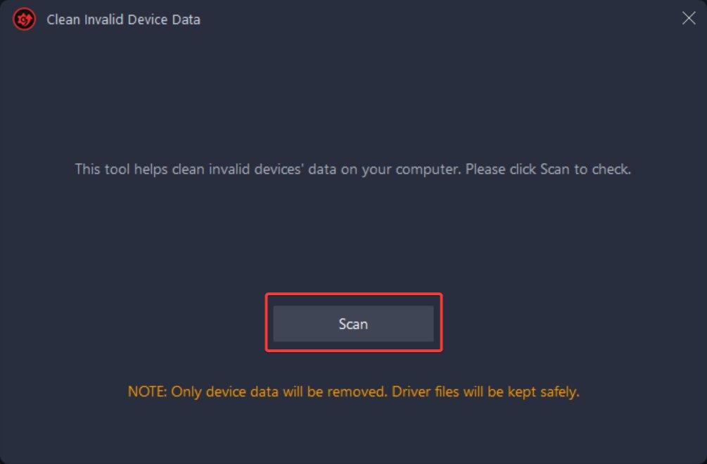
So its recommended to do regular cleanup of the unplugged device data. The easy way to do it is use tools provided in the Driver Booster app.
From the tool section, run the Clean invalid Device data tool.

Click Scan to find the invalid device data entries.
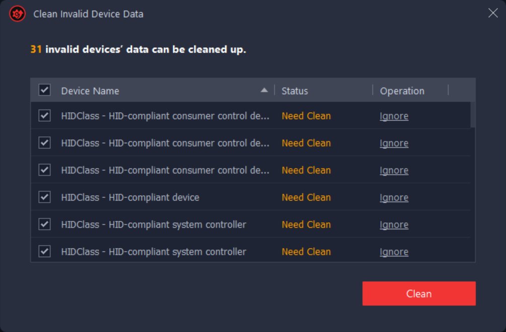
The user may clean all of the invalid entries or manually select the ones that is causing the issue.
E. Proper installation of the hardware components in the computer
In the desktop computer, the user must make sure that hardware components have been correctly and firmly installed. The power and data transfer cables must be connected properly. Any loose or improper connection would mean slower or faulty performance of the computer.
F. WiFi Adapter Device and Deployment
If you are using a USB WiFi Adapter then make sure it is firmly connected to the USB port.
1. USB Port In which the USB WiFi Adapter has been plugged
The USB port into which the WiFi adapter has been plugged can affect the data transfer speed and network latency.
- For example, a USB 2.0 port supports a maximum speed of 480 Mbps. A USB WiFi adapter plugged into a USB 2.0 port will support a maximum data transfer speed of 480 Mbps.
- Plug the USB WiFi adapter into the USB port of the computer which is supported by the adapter. Check the USB specification of the WiFi adapter provided by the manufacturer.
- Example: If the USB WiFi adapter supports USB 3.0 then connect it to the USB 3.0 port on the computer.
2. WiFi Adapter Device
- Avoid buying a Nano/Mini WiFi adapter. The range of these wifi adapters is not good.
- If possible buy a high-gain WiFi USB Adapter.
- If possible buy an 802.11ac WiFi adapter. It uses a 5Ghz frequency which is generally free from interference.
3. WiFi Adapter deployment
- To get better signal strength and link speed you need to keep the WiFi adapter at close range of the WiFi router.
- When the WiFi adapter is in a direct line of sight to the WiFi router then the signal strength received by the WiFi adapter is very good and there is the least issue of network latency. The connection between the WiFi adapter and the WiFi router is best when they are kept in the same room.
- When the WiFi adapter is kept in a room which is adjacent to the room in which the WiFi router has been kept then it starts affecting the data transfer speed and latency.
- If possible use a USB extension wire which is helpful in positioning the WiFi adapter at the desired location. It also helps in proper orientation of the WiFi adapter antenna to align with the WiFi router antenna.
- Keep the WiFi adapter away from obstructions such as walls, metal objects, and other electrical equipment.
- Positioning the WiFi adapter such that it is at least 3 ft away from other electrical devices. It’s better to relocate the electrical devices away from the WiFi adapter.
- Position the WiFi adapter at least 1.5 ft away from the corners of the building.
- Position the WiFi adapter such that there is least or no obstruction between the WiFi adapter and the WiFi router. Only walls of the building is an unavoidable obstruction between the WiFi adapter and WiFi router when they are located in separate rooms of the building. You should try to avoid all other obstructions.
G. Windows Power Management Settings
- In Windows OS, open Control Panel.
- Select Control Panel > Power Options.

- Click on “Change plan settings” of the active power plans.

- Click on “Change advanced power settings“

- For maximum WiFi Performance do the following:
- Set Wireless Adapter Settings > Power Saving Mode > Maximum performance.
- If the WiFi adapter is connected to the PCI Express then set PCI Express > Link Power State Management > Off.
- Click on Apply.


H. WiFi Router Deployment
- It is recommended to place the WiFi router in the middle of the coverage area, which helps in maximizing the signal strength for each of the receiving WiFi clients(adapters). Placing the WiFi router in the middle is not necessary if the coverage area is small.
- Keep the WiFi Router away from obstructions such as concrete walls, large metallic objects, and electrical equipment’s.
- Check the WiFi router manual for the correct orientation of the WiFi router antenna.
Related Articles:
I. WiFi Router/Access Point Configuration
To achieve low latency do the following in the 2.4 GHz band 802.11N wireless setting in the WiFi Router if it is available:
- Channel bandwidth: Set the channel bandwidth to 20 MHz for the 802.11N network. Using 20 Mhz channel bandwidth instead of 40 MHz helps in avoiding interference caused by other WiFi networks operating in the same channels.
- Wireless Mode: N Only
- IGMP Snooping: Enable
- Multicast Rate: HTMIX 13, HTMIX 19.5
- Preamble Type: Long
- RTS Threshold: 700
- DTIM Interval: 1
- Beacon Interval: 200
- WMM ASPD: Disable
- Explicit Beamforming: Disable
- Implicit beamforming: Disable
- Transmitting Power/Transmit Power Control:
- Good/80%
- Highest/Performance/100%.
To achieve low latency do the following in the 5 GHz band 802.11AC wireless setting in the WiFi Router setting if it is available:
- Channel bandwidth: 40 MHz or 80 MHz
- IGMP Snooping: Enable
- Multicast Rate: HTMIX 13, HTMIX 19.5
- Preamble Type: Long
- RTS Threshold: 1000
- DTIM Interval: 1
- Beacon Interval: 200
- WMM ASPD: Disable
- Explicit Beamforming: Disable
- Implicit beamforming: Disable
- Universal beamforming: Disable
- Transmitting Power/Transmit Power Control:
- Good/80%
- Highest/Performance/100%.
2. WiFi Network issues
A. WiFi Network Connection establishment issues
Establishing a Wi-Fi connection between a client device (e.g., smartphone, laptop) and a router involves several steps: authentication, association, IP address assignment, and network handshake. Failures at any stage can prevent a successful connection.
Wi-Fi connection failures often stem from mismatched configurations and signal issues. For a connection to establish between the WiFi adapter and WiFi router, it is necessary that both devices have been configured correctly. The WiFi adapter device capability must match the parameters of wireless network hosted by the router.
Some of the reasons the WiFi adapter is unable to connect to the WiFi network hosted by the WiFi Router are:
1. Authentication Failures
Causes:
- Incorrect Wi-Fi password: Typographical errors or outdated saved credentials.
- Security protocol mismatch: Router uses WPA3 or WPA2-Enterprise, but the client only supports WPA2-PSK or WEP.
- Certificate issues (enterprise networks): Expired or misconfigured certificates for WPA2/WPA3-Enterprise (e.g., EAP-TLS, PEAP).
Solutions:
- Re-enter the Wi-Fi password on the client device.
- Ensure the router’s security protocol matches client capabilities (e.g., use WPA2-AES for broad compatibility).
2. Association Failures
Causes:
- Unsupported Wi-Fi standard: Client uses 802.11b/g, but the router operates in 802.11ac/n-only mode.
- Hidden SSID: The network name (SSID) is not broadcasted, requiring manual entry.
- MAC filtering: The router blocks the client’s MAC address.
Solutions:
- Make sure that the WiFi client device support the 802.11n/ac standard.
- Manually enter the SSID and security details if the network is hidden.
- Disable MAC filtering or add the client’s MAC address to the router’s allowlist.
3. IP Address Assignment Issues
Causes:
- DHCP server failure: Router’s DHCP fails to assign an IP address.
- IP conflict: Another device on the network uses the same IP address.
- Static IP misconfiguration: Client uses a static IP outside the router’s subnet.
Solutions:
- Restart the router to reset the DHCP server.
- Configure the client to use DHCP instead of a static IP.
- Check for IP conflicts using the router’s admin interface (e.g., DHCP lease table).
4. Signal/Radio Issues
Causes:
- Weak signal strength: Client is out of range or obstructed by walls/metal objects.
- Band mismatch: Client supports only 2.4 GHz, but the router’s 2.4 GHz radio is disabled.
Solutions:
- Move the client closer to the router or reposition the router.
- Enable the 2.4 GHz band on the router for older devices.
5. Channel number incompatibility
The WiFi adapter won’t be able to connect to the WiFi network, if it does not support the channel which is being used to host the WiFi network by the WiFi router. This is most evident in the 5 GHz WiFi AC network.
For example, the 802.11ac wifi adapter support Channels no. 36, 40, 44, and 48 in the 5 GHz bands. It will not be able to connect to the WiFi network hosted in Channel no. 52, 56, 60, 64, 149, 153, 157, 161, and 165 in the 5 GHz bands.
6. Channel width incompatibility
The WiFi adapter does not support the channel width which has been used to host the WiFi network by the WiFi router. This is more evident in the 5 GHz band WiFi network. For example, the 802.11ac adapter support only channel bandwidth of up to 40 MHz in the 5 GHz band. It is unable to connect to a WiFi network hosted with a channel width of 80 MHz or 160 MHz.
7. Interference and Congestion
The WiFi router has been configured to host a WiFi network at a particular channel that is highly congested. In such a situation, the WiFi adapter will connect to the WiFi network with a huge delay or the connection will remain unstable. The solution is use a least congested channel to host the WiFi network by the WiFi router. This is more evident in 2.4 GHz band.
8. Old Driver of the WiFi network adapter
Old version of the driver for the network adapter may cause the issue of not being able to connect to the WiFi network. The reason is that the old driver is incompatible with the Windows operating system or it lacks the new functionality required to connect the wireless network.
The solution is simple to use the newer version of the driver.
B. WiFi Network Connection drop and stability issue
Frequent disconnections between a Wi-Fi client device (e.g., smartphone, laptop) and a router can stem from a wide range of issues, spanning hardware, software, configuration, and environmental factors.
1. Interference and Channel Congestion
- Cause:
- Overlapping Wi-Fi networks on the same channel (especially in dense areas like apartments). When a wireless channel is utilized by multiple wireless network then it causes co-channel interference. When the channel utilization is high the Wireless client may end up in dropping the connection.
- Non-Wi-Fi interference from devices like microwaves, Bluetooth gadgets, baby monitors, or cordless phones (common on the 2.4 GHz band).
- Physical obstructions (walls, metal objects, mirrors) weakening the signal.
- Solutions:
- Switch to a less congested channel using a Wi-Fi analyzer tool (e.g., 5 GHz band, which has more channels and less interference).
2. WiFi driver stability issue
If the WiFi driver is not stable then you will witness frequent disconnection.
Using another version of the driver that is stable will solve the problem.
3. Using non-standard features
There are some features implemented in WiFi router and the WiFi adapter that is not defined in 802.11N and 802.11AC wireless standard. If these features are enabled, it will may lead to unstable connection. With these non standard features enabled, the wireless connection will work fine for some time while other times it will lags heavily or the connection gets disconnected.
It is highly recommenced to disable each of the non-standard features.
4. WiFi adapter overheating
If the chipset in the WiFi adapter overheats due to high rate of data transfer, the it will choose to disconnect from the WiFi network to prevent it from further overheating. This is more evident in USB WiFi adapter.
5. USB Wi-Fi adapter power supply issue
When the USB WiFi adapter is connected to a port of the USB extension Hub_1. At the same time, other USB devices(USB HDD, USB Keyboard, etc), are connected to the same USB extension hub_1. This causes the distribution of power among the USB WiFi adapter and other USB devices. This may leave the USB WiFi adapter with extremely low power to operate which causes it to drop the connection with the WiFi router.
- USB 2.0 port can deliver a maximum power of 2.5W.
- USB 3.0 / USB 3.1 can deliver maximum power of 4.5 W.
6. Switching between USB 2 and USB 3
The modern USB WiFi adapter supports USB 3.0 connectivity. At the same time it can switch to USB 2.0 connectivity.
If the driver or the utility apps that came along with it causes switching between USB 3.0 and USB 2.0, then the connection between WiFi adapter and the router will be lost for few seconds during switching process.
One way to stabilize it is to configure the WiFi adapter to connect it it only 2.4 GHz band or 5 GHz band.
7. Network Overload
- Cause:
- Too many connected devices exceeding the router’s capacity (common in older routers with limited RAM/CPU).
- Bandwidth-heavy activities (4K streaming, large downloads) congesting the network.
- Solutions:
- Limit the number of simultaneous connections.
- Use Quality of Service (QoS) settings to prioritize critical traffic (e.g., video calls).
8. Signal Strength and Range Limitations
- Cause:
- The client is too far from the router, leading to weak signal (RSSI < -70 dBm).
- Dead zones caused by building materials (concrete, brick) or large appliances.
Other online FAQs
C. WiFi network throughput and latency Issues
Wi-Fi throughput (data transfer rate) and latency (delay) are critical performance metrics that impact user experience, especially for real-time applications like gaming, video conferencing, and streaming.
Throughput:
- Definition:
- Throughput refers to the actual amount of data that successfully transfers over a Wi-Fi network within a specific time frame. It’s the “real-world” speed you experience.
- It’s often measured in megabits per second (Mbps).
- Factors Affecting Throughput:
- Bandwidth: The maximum capacity of the Wi-Fi connection.
- Signal Strength: Weak signals result in lower throughput.
- Interference: Other electronic devices or overlapping Wi-Fi networks can reduce throughput.
- Network Congestion: Too many devices using the same network can cause slowdowns.
- Router Capabilities: The router’s processing power and Wi-Fi standards (802.11ac, 802.11ax, etc.) influence throughput.
- Distance: The distance between the client device and the router.
- Obstacles: walls, and other obstructions.
Latency:
- Definition:
- Latency is the delay between when a data packet is sent and when it’s received. It’s the “lag” you experience.
- It’s often measured in milliseconds (ms).
- Factors Affecting Latency:
- Distance: Longer distances increase latency.
- Network Congestion: High traffic can cause delays.
- Router Processing: Routers with slow processing can increase latency.
- Interference: Interference can cause retransmissions, increasing latency.
- Wi-Fi Standards: Older Wi-Fi standards may have higher latency.
- Bufferbloat: This is a condition in which excess buffering of packets in a network device leads to high latency.
1. Configuration Issues
Causes:
- Suboptimal channel width: Wide channels (e.g., 40 MHz on 2.4 GHz and 160 MHz on 5 GHz) cause interference; narrow channels limit throughput.
- Outdated router firmware: Bugs or inefficiencies in older firmware versions.
- QoS misconfiguration: Poor traffic prioritization (e.g., background downloads starving video calls).
- Legacy protocols enabled: Mixed-mode networks (802.11b/g/n) slow down modern devices.
Solutions:
- Set 2.4 GHz channel width to 20 MHz and 5 GHz to 80/160 MHz (if interference-free).
- Update router firmware to the latest stable version.
- Enable QoS to prioritize latency-sensitive traffic (e.g., VoIP, gaming).
- Disable legacy protocols (e.g., 802.11b/g) in favor of Wi-Fi 5 (802.11ac) or Wi-Fi 4 (802.11n)
2. Hardware Limitations
Causes:
- Overloaded router CPU/RAM: Struggles with high device counts or bandwidth-heavy tasks.
- Antenna issues: Poorly oriented or low-gain antennas reduce signal quality.
Solutions:
- Use external antennas (if supported) and orient them properly.
- Offload tasks to a dedicated access point or mesh system in large homes/offices.
3. Co-channel Interference
Wi-Fi co-channel interference occurs when multiple wireless networks or devices operate on the same frequency channel, leading to signal overlap, congestion, and degraded performance.
Your WiFi network experiences co-channel interference from other WiFi networks in the area when these conditions are met:
- Other WiFi networks in the area use the same channel to host the WiFi network as your own WiFi network.
- The signal strength of these other wifi networks is strong in the coverage area of your WiFi network.
Causes of Co-Channel Interference
- Dense Wi-Fi Deployments:
- Common in apartments, offices, or urban areas where many routers use the same limited channels (especially in the 2.4 GHz band).
- Legacy 2.4 GHz Band Usage:
- The 2.4 GHz band has only 3 non-overlapping channels (1, 6, 11 in 20 MHz width). When multiple Wi-Fi access points (APs) in close proximity use the same channel, their signals interfere with each other.
- High-Density Environments:
- Public hotspots, stadiums, or conference centers with many overlapping networks.
- High Transmit Power:
- APs with high transmit power can cause interference to devices on the same channel, even if they are relatively far away.
- Microwave ovens, car alarms, cordless phones, baby monitor, bluetooth devices or wireless video cameras generates wireless signal in 2.4 GHz band and causes interference to the wireless network if they are placed in coverage area of network..
Effects of Co-Channel Interference
- Reduced Throughput:
- Devices compete for airtime, causing CSMA/CA (Carrier-Sense Multiple Access with Collision Avoidance) delays and lower data rates.
- Increased Latency:
- Frequent packet retransmissions due to collisions degrade real-time applications (e.g., VoIP, gaming).
- Unstable Connections:
- Intermittent disconnections or “stuttering” in video streams.
- Lower Signal-to-Noise Ratio (SNR):
- Even with strong signal strength (RSSI), interference raises noise levels, reducing effective SNR.
- Channel Contention:
- Devices wait longer to transmit data, increasing airtime unfairness (e.g., older 802.11b/g devices hogging airtime).
Solutions to Mitigate Co-Channel Interference
I) Optimize Channel Selection
- Use 5 GHz Band:
- The 5 GHz band offers 24 non-overlapping channels (vs. 3 in 2.4 GHz). Prioritize this band for high-throughput devices.
- Manual Channel Assignment:
- Use tools like WiFi Analyzer to identify the least congested channel and manually configure routers/APs.
- Some of the good Android based WiFi scanners are:
- Avoid DFS Channels (Dynamic Frequency Selection):
- Some 5 GHz channels (e.g., 52–144) are shared with radar systems. While they reduce congestion, not all clients support DFS.
II) Reduce Overlap in 2.4 GHz
- Stick to Channels 1, 6, or 11 (20 MHz width) to minimize adjacent-channel interference.
- Avoid using 40 MHz channels in 2.4 GHz, as they span multiple non-overlapping channels and worsen congestion.
III) Adjust Transmit Power
- Lower the router’s transmit power to limit its coverage area, reducing overlap with neighboring networks. This is especially useful in multi-AP setups (e.g., enterprise networks).
IV) Use Channel Bonding Wisely
- 5 GHz Band:
- Use 80 MHz or 160 MHz channels only in interference-free environments (e.g., rural areas).
- 2.4 GHz Band:
- Avoid channel bonding entirely (stick to 20 MHz).
V) Physical Placement Optimization
- Position APs/routers to minimize coverage overlap with neighboring networks. Use directional antennas to focus signals.
Key Takeaways
- Co-channel interference is unavoidable in dense environments but manageable with proper planning.
- Prioritize the 5 GHz band and manual channel optimization.
Related links:
- The possible sources of interference
- https://blogs.arubanetworks.com/industries/an-intro-to-co-channel-interference/
- https://www.ekahau.com/blog/channel-planning-best-practices-for-better-wi-fi/
- Troubleshoot the speed of your NETGEAR USB wireless adapter
- The Best 5GHz Wi-Fi Channel
- Brief introduction of DFS function
4. WiFi Signal strength
Wireless signal strength directly influences both throughput (data transfer rate) and latency (delay) in 802.11 networks.
- Throughput: Directly tied to signal strength via modulation schemes, MIMO streams, and channel width. Downlink often outperforms uplink due to AP hardware advantages.
- Latency: Weak signals increase retransmissions, ACK delays, and airtime contention. Uplink latency is more susceptible to client-side signal weakness.
I) Signal Strength and Data Rates
- Signal Metrics:
- RSSI (Received Signal Strength Indicator): Measured in dBm, higher (less negative) values indicate stronger signals.
- SNR (Signal-to-Noise Ratio): Ratio of signal power to background noise. Higher SNR enables higher data rates.
- Modulation Schemes:
- Strong signal (high SNR): Supports advanced modulation (e.g., 256-QAM), maximizing throughput.
- Weak signal (low SNR): Forces fallback to simpler schemes (e.g., QPSK), reducing throughput.
- Example: A drop from -60 dBm (strong) to -80 dBm (weak) might halve the PHY rate (e.g., 866 Mbps to 400 Mbps).
II) Throughput Degradation
- Uplink vs. Downlink:
- Downlink (AP to client): APs typically have stronger transmitters, maintaining higher data rates even at lower client signal strength.
- Uplink (Client to AP): Client devices (e.g., smartphones) with weaker transmitters suffer more. A weak client signal forces the AP to use lower modulation, reducing uplink throughput disproportionately.
- Channel Width:
- Wide channels (80/160 MHz) offer higher throughput but are more prone to interference. Weak signals may necessitate narrower channels (20 MHz), reducing capacity.
III) Latency Increases
- Retransmissions: Weak signals cause packet loss, triggering retransmissions. Each retry adds latency (e.g., 50–100 ms per retry in TCP).
- Airtime Contention: Low signal extends transmission time per packet (due to slower modulation), increasing airtime usage. This delays other packets, raising latency for all devices.
- ACK Delays: Weak signals slow acknowledgment (ACK) frames, increasing round-trip time (RTT). For real-time apps (VoIP, gaming), this causes jitter.
IV) MIMO and Spatial Streams
- Impact: Strong signals enable multiple spatial streams (MIMO), multiplying throughput. Weak signals reduce stream count (e.g., 4×4 MIMO → 2×2), cutting throughput.
- Uplink Limitation: Clients often have fewer antennas than APs. Weak uplink signals may disable MIMO entirely, bottlenecking uplink throughput.
V). MAC Layer Behavior (CSMA/CA)
- Carrier Sense: Weak signals increase “false busy” medium detection (due to noise), forcing devices to wait longer (backoff periods), increasing latency.
- Airtime Fairness: Legacy devices (802.11b/g) consuming excessive airtime on weak links starve modern devices of bandwidth.
VI). Asymmetry in Uplink/Downlink
- Example: A laptop with a weak Wi-Fi connection might achieve 200 Mbps downlink (AP’s strong signal) but only 20 Mbps uplink (laptop’s weak transmitter).
- Power Constraints: Mobile devices often limit transmit power to save battery, exacerbating uplink weakness.
The Transmit power in both the WiFi router and WFi adapter should be set to the second highest value most scenario of deployment. If the coverage area needs to be maximum then only the transmit power must be set to highest value.
5. USB port connection version of the USB WiFi network adapter
If the dual band USB WiFi adapter is connecting to the computer USB hub using USB 2.0 version, then the maximum data transfer limit will be 480 Mbps. This data transfer speed is insufficient for maintaining connection to the 802.11ac wireless network. So the connection will drop to 802.11n network.
If the USB WiFi adapter is connecting to the computer USB hub using USB 3.0 version, then the maximum data transfer limit will be 5 Gbps. This data transfer speed is sufficient for maintaining connection to the 802.11ac wireless network supporting up to 3 Gbps data transfer.
3. Understanding various WiFi adapter terms
Wireless Network
A Wireless Network in the context of the IEEE 802.11 standard, commonly known as WiFi, refers to a communication system that enables devices to exchange data wirelessly using radio frequencies in the 2.4 GHz, 5 GHz, or 6 GHz bands, following the protocols and specifications defined by the 802.11 family of standards. These standards, including amendments like 802.11n (High Throughput, HT), 802.11ac (Very High Throughput, VHT), 802.11ax (WiFi 6/6E), 802.11d, and 802.11h, define how devices such as laptops, smartphones, IoT devices, and access points (APs) communicate over the air.
Definition of a Wireless Network (802.11 Context)
- Core Concept: An 802.11 wireless network is a local area network (LAN) that uses radio waves to connect devices without physical cables, enabling data communication within a specific coverage area (e.g., home, office, or public hotspot). It operates under the IEEE 802.11 standards, which specify the physical (PHY) and medium access control (MAC) layers for wireless communication.
- Key Characteristics:
- Wireless Medium: Uses unlicensed radio frequency bands (2.4 GHz, 5 GHz, 6 GHz) for communication, avoiding the need for wired infrastructure.
- Standards-Based: Governed by 802.11 protocols (e.g., 802.11a/b/g/n/ac/ax/be), ensuring interoperability across devices from different manufacturers.
- Topology: Typically operates in infrastructure mode (devices connect to an AP) or ad-hoc mode (peer-to-peer connections without an AP).
- Applications: Supports diverse use cases, including internet access, file sharing, streaming, gaming, and IoT communication (e.g., VHT 2.4G IoT for high-throughput IoT devices).
- Purpose:
- Provide flexible, scalable, and mobile connectivity for devices like smartphones, laptops, IoT sensors, and cameras.
- Enable features like WoWLAN for remote wake-up, packet coalescing for efficiency, and VHT for high data rates.
- Ensure compliance with global regulations via 802.11d and 802.11h for seamless operation across regions.
Components of an 802.11 Wireless Network
- Stations (STAs):
- Devices with WiFi capability, such as laptops, smartphones, tablets, or IoT devices (e.g., smart cameras using VHT 2.4G IoT).
- Each STA has a WiFi adapter (network interface card, NIC) that supports 802.11 protocols, including features like HT, VHT, and WoWLAN.
- Access Points (APs):
- Central devices that coordinate communication, connect STAs to a wired network (e.g., the internet provided by ISP), and broadcast management frames like beacons.
- Support features like 802.11d (country-specific regulations), 802.11h (DFS/TPC in 5 GHz), and VHT for high-throughput communication.
- Wireless Medium:
- Radio frequency bands (2.4 GHz, 5 GHz, 6 GHz) divided into channels (e.g., 20 MHz, 40 MHz, 80 MHz, 160 MHz).
- Subject to multi-path fading, interference, and regulatory constraints enforced by 802.11d and 802.11h.
- Basic Service Set (BSS):
- A group of STAs connected to a single AP, identified by a BSSID (MAC address of the AP).
- Multiple BSSs can form an Extended Service Set (ESS), sharing the same SSID for seamless roaming.
- Distribution System (DS):
- Connects multiple APs to form a larger network, typically via wired Ethernet, enabling communication between BSSs.
- Management Frames:
- Include beacon frames (sent at the beacon interval), probe requests/responses, association frames, and 802.11h channel switch announcements, used to manage network operation and features like WoWLAN.
Operational Mechanisms
802.11 wireless networks operate using a combination of PHY and MAC layer protocols, enhanced by amendments like 802.11n (HT), 802.11ac (VHT), 802.11d, and 802.11h:
- Carrier Sense Multiple Access with Collision Avoidance (CSMA/CA):
- Devices listen to the channel before transmitting to avoid collisions, using inter-frame spaces (e.g., SIFS, DIFS) and random backoff.
- Packet coalescing (e.g., A-MPDU, A-MSDU) reduces the number of transmissions, improving efficiency.
- Channel Access and Bandwidth:
- Channels are allocated in 20 MHz, 40 MHz (HT), or 80/160 MHz (VHT) widths, with VHT 2.4G IoT using 20/40 MHz in the 2.4 GHz band.
- 802.11d ensures channel selection complies with regional regulations, while 802.11h enforces DFS for radar avoidance in 5 GHz.
- Modulation and Coding:
- Uses modulation schemes like BPSK, QPSK, 16-QAM, 64-QAM (HT), or 256-QAM (VHT) to encode data.
- Higher-order modulation (e.g., 256-QAM in VHT 2.4G IoT) requires high SNR, supported by beamforming and transmit power.
- LDPC codes enhance error correction, particularly for high-order modulation.
- Power Management:
- Features like WoWLAN allow devices to enter low-power states, waking only for specific events.
- 802.11h Transmit Power Control (TPC) adjusts transmit power to minimize interference and power consumption in 5 GHz.
- Regulatory Compliance:
- 802.11d provides the Country Information Element to adapt to regional channel and power limits.
- 802.11h implements DFS and TPC in the 5 GHz band to avoid radar interference and optimize power usage. TPC adjusts transmit power to minimize interference, benefiting battery-powered devices like IoT sensors.
- Frame Aggregation:
- Packet coalescing (via A-MPDU/A-MSDU) combines packets to reduce overhead, critical for HT and VHT in dense environments.
- Beamforming:
- Focuses transmit power toward specific devices, improving SNR for HT and VHT in multi-path fading environments.
- Enhances VHT 2.4G IoT performance by supporting 256-QAM in the congested 2.4 GHz band.
- Guard Interval:
- Uses a guard interval (400 ns or 800 ns) to prevent inter-symbol interference (ISI) in multi-path fading environments, enhancing reliability for HT and VHT.
Types of 802.11 Wireless Networks
- Infrastructure Mode:
- Most common setup, where STAs connect to an AP forming a BSS.
- Supports features like WoWLAN, VHT, and packet coalescing for efficient communication.
- Used in homes, offices, and public hotspots.
- Ad-Hoc Mode (Independent BSS, IBSS):
- Peer-to-peer network where STAs communicate directly without an AP.
- Limited support for advanced features like VHT, WoWLAN, or 802.11h.
- Mesh Networks (802.11s):
- APs form a self-configuring network, extending coverage and supporting IoT applications.
- Leverages HT and VHT for high throughput and packet coalescing for efficiency.
- WiFi Direct:
- Allows direct device-to-device communication, often used for IoT or file sharing.
- May support HT or VHT 2.4G IoT for higher data rates.
Evolution and Standards
The 802.11 standard has evolved through amendments, each addressing specific needs:
- 802.11a (1999): 5 GHz, 54 Mbps, OFDM, limited range.
- 802.11b (1999): 2.4 GHz, 11 Mbps, DSSS, longer range but interference-prone.
- 802.11g (2003): 2.4 GHz, 54 Mbps, OFDM, compatible with 802.11b.
- 802.11n (2009, HT): 2.4/5 GHz, up to 600 Mbps, MIMO, 40 MHz channels, frame aggregation.
- 802.11ac (2013, VHT): 5 GHz, up to 6.9 Gbps, 80/160 MHz, 256-QAM, MU-MIMO.
- 802.11ax (2019, Wi-Fi 6): 2.4/5/6 GHz, up to 9.6 Gbps, OFDMA, 1024-QAM, TWT.
- 802.11be (Wi-Fi 7): Up to 46 Gbps, 320 MHz, 4096-QAM, MLO.
- Wireless station(STA) : A computing device that has a single/multiple wireless network card installed to it, that supports 801.11 wireless standard. It includes Wireless client devices and access points.
- WiFi enabled client device/Endpoints: These are wireless stations that are engaged in data communication only through one Access point. Endpoints can be computers, mobile smartphones, printers. Other terms used interchangeably for it is WiFi adapter, wireless Network Interface Card (NIC).
- Attenuation – a loss in force or intensity – As radio waves travel in media such as coaxial cable attenuation occurs.
- BER – Bit Error Rate – the fraction of bits transmitted that are received incorrectly.
- PER – Packet error rate
- Channel Bonding – act of combining more than one channel for additional bandwidth
- dBd – abbreviation for the gain of an antenna system relative to a dipole
- dBi – abbreviation for the gain of an antenna system relative to an isotropic antenna
- dBm – decibels milliwatt — abbreviation for the power ratio in decibels (dB) of the measured power referenced to one milliwatt of transmitted RF power.
- Multipath – refers to a reflected signal that combines with a true signal resulting in a weaker or some cases a stronger signal.
- mW – milliwatt a unit of power equal to one thousandth of a watt (usually converted to dBm)
- Noise Floor – The measure of the signal created from the sum of all the noise sources and unwanted signals appearing at the receiver. This can be adjacent signals, weak signals in the background that don’t go away, electrical noise from electromechanical devices etc.
- Receiver Sensitivity – The minimum received power needed to successfully decode a radio signal with an acceptable BER. This is usually expressed in a negative number depending on the data rate. For example the AP-1140 Access Point requires an RF strength of at least negative -91 dBm at 1 MB and an even higher strength higher RF power -79 dBm to decode 54 MB
- Receiver Noise Figure – The internal noise present in the receiver with no antenna present (thermal noise).
- SNR – Signal to Noise Ratio – The ratio of the transmitted power from the AP to the ambient (noise floor) energy present.
- Radio signal: a high-frequency electromagnetic wave that has long-distance transmission capabilities. Radio signals provide transmission media for 802.11-compliant WLANs. Radio signals described in this document are electromagnetic waves in the 2.4 GHz or 5 GHz frequency band.
High Throughput(HT)
HT stands for High Throughput in the context of IEEE 802.11 WiFi standards. It refers to a set of enhancements introduced in the 802.11n standard (WiFi 4) to significantly increase data rates and improve network efficiency compared to earlier standards like 802.11a/b/g. High Throughput (HT) is a feature set in the 802.11n standard that enables higher data rates (up to 600 Mbps theoretically) by introducing advanced techniques like Multiple-Input Multiple-Output (MIMO), wider channel bandwidths, and improved modulation. HT operates in both the 2.4 GHz and 5 GHz bands, making it versatile for various applications, including early IoT devices.
HT in 802.11 Standards
HT is specific to 802.11n but provides the foundation for later standards like 802.11ac (VHT) and 802.11ax:
- 802.11n (WiFi 4):
- Introduced HT in 2009, supporting both 2.4 GHz and 5 GHz bands.
- Theoretical maximum data rate of 600 Mbps (4×4 MIMO, 40 MHz, 64-QAM, 400 ns guard interval).
- Optional features include implicit beamforming and Power Save Multi-Poll (PSMP), precursors to VHT’s explicit beamforming and WoWLAN.
Mechanisms of HT
HT achieves high throughput through several key techniques:
- Multiple-Input Multiple-Output (MIMO):
- Uses multiple antennas for transmitting and receiving multiple data streams simultaneously (e.g., 2×2 MIMO for two streams).
- Increases throughput linearly with the number of spatial streams (e.g., 150 Mbps per stream with 40 MHz, 64-QAM).
- 40 MHz Channels:
- Doubles the channel width from 20 MHz (802.11a/g) to 40 MHz, doubling the data rate (e.g., 150 Mbps vs. 75 Mbps for 1×1 MIMO, 64-QAM).
- In the 2.4 GHz band, 40 MHz channels are limited by spectrum availability and interference, often making 20 MHz more practical.
- 64-QAM Modulation:
- Encodes 6 bits per symbol, compared to 4 bits (16-QAM) in 802.11a/g, increasing data rates by 50%.
- Requires higher SNR than lower-order modulation, making beamforming and LDPC (optional in 802.11n) critical.
- Frame Aggregation:
- Uses A-MPDU (Aggregate MAC Protocol Data Unit) and A-MSDU (Aggregate MAC Service Data Unit) to combine multiple packets into a single frame, reducing overhead, similar to packet coalescing.
- Improves efficiency for small packets, common in IoT applications.
- Short Guard Interval:
- Reduces the guard interval from 800 ns to 400 ns, increasing throughput by ~11% in environments with low multi-path fading.
- Implicit Beamforming (Optional):
- Focuses signals toward clients to improve SNR and range, a precursor to VHT’s explicit beamforming.
- Block Acknowledgment:
- Acknowledges multiple packets in a single Block ACK, reducing control overhead compared to individual ACKs.
Very High Throughput (VHT)
It is a key feature introduced in the IEEE 802.11ac standard (WiFi 5). VHT, or Very High Throughput, is a set of enhancements in the 802.11ac standard (and later standards) that enable gigabit-level data rates by leveraging wider channels, advanced modulation, and multi-user techniques. It is primarily designed for the 5 GHz band but has been extended non-standardly to the 2.4 GHz band in some implementations (e.g., VHT 2.4G ).
Purpose:
- Increase Data Rates: Achieve higher throughput for bandwidth-intensive applications like 4K/8K video streaming, gaming, and large file transfers.
- Improve Efficiency: Support multiple devices in dense environments through MU-MIMO and efficient channel utilization.
- Enable Global Operation: Comply with regulatory requirements (via 802.11d and 802.11h) to operate legally across regions.
- Support IoT: In VHT 2.4G IoT, provide higher throughput for data-intensive IoT devices (e.g., security cameras) in the 2.4 GHz band.
Mechanisms of VHT
VHT leverages several techniques to achieve high throughput:
- Wider Channel Bandwidths:
- Supports 80 MHz and 160 MHz channels in the 5 GHz band, doubling or quadrupling throughput compared to 40 MHz (802.11n).
- In VHT 2.4G IoT, limited to 20 MHz or 40 MHz due to the 2.4 GHz band’s ~80 MHz total spectrum.
- Higher-Order Modulation:
- 256-QAM encodes 8 bits per symbol, offering ~33% higher data rates than 64-QAM (6 bits per symbol).
- Requires high SNR, making beamforming, LDPC, and optimal transmit power critical.
- MU-MIMO:
- Allows the AP to transmit to multiple devices simultaneously, improving efficiency in dense environments.
- In VHT 2.4G IoT, MU-MIMO is less common but supported by some advanced chipsets.
- Frame Aggregation:
- Uses A-MPDU and A-MSDU (via packet coalescing) to combine multiple packets into a single frame, reducing overhead.
- Critical for VHT 2.4G IoT to minimize airtime usage in the congested 2.4 GHz band.
- Beamforming:
- Focuses transmit power toward specific devices, improving SNR and range, especially for high-order modulation like 256-QAM.
- LDPC:
- Enhances error correction for 256-QAM and wide channels, mitigating errors from multi-path fading or interference.
Access controller (AC)
The term Access controller is defined for some network functionalities that a device is capable of doing. Access controller is a device that controls and manages all of the access points (APs) on a WLAN in the centralized architecture.
Generally in a home WiFi network, the WiFi router acts both as Access Controller and Access Point.
When additional APs are connected to the AC, the AC manages and controls APs in a centralized manner through Control and Provisioning of Wireless Access Points (CAPWAP) tunnels. CAPWAP tunnels provide the following functions:
- Maintain the running status of APs and the AC.
- Help the AC manage APs and deliver configurations to APs.
- Transmit service data to the AC for centralized forwarding.
Access controller manages allocation of IP addresses to the client devices connected the the wireless network.
WiFi Router
WiFi router device supports multiple functionality.
- It supports the function of Access Point to establish a wireless network(wireless LAN).
- It supports function to connect with ISP using modem and access the internet.
- It supports function to work as network router by routing IP data packets between ISP and LAN.
- It supports function to establish a wired LAN using Ethernet ports.
- It can act as Access Controller when it connected to Access Points and a wireless network has been created to support wireless roaming.
Wireless Access point (AP)
A device that provides 802.11-compliant wireless access for WiFi enabled client device. The Access Point provides only reliable, high-performance wireless connections to WiFi client devices and depends on an Access Controller to provide other functions. The Access point facilitate data transmission between the multiple WiFi enabled devices connected to it.
The Access Point(AP) is connected to Access Controller(AC) using Distribution System(DS). The connectivity between Access point and Access controller may be a wired (Ethernet) or wireless when the AP and AC is two separate device. In a router the AP and AC functionality is inbuilt in one device.
The Connection between the Access point and Access controller is established using CAPWAP tunnel protocol. This facilitates the data transmission between WiFi enabled devices and the Access Controller. The Access controller may provide further data connectivity to other WLANs or to the internet.
An AP can go online in IPv4 or IPv6 mode, and the IPv4 mode takes precedence. The CAPWAP tunnel supports IPv4 and IPv6, but cannot use them concurrently. The AC can only manage APs using either the IPv4 mode or IPv6 mode. The CAPWAP tunnel supports encapsulation of IPv4 and IPv6 packets, but can encapsulate one type of packets at one time, namely, the CAPWAP tunnel can transmit only one type of packets each time.
In a home WiFi network, the WiFi router can act as an Access point if it has such a inbuilt feature.
Access Point is also called Wireless Termination Points (WTPs)
SSID
The Service Set Identifier (SSID) is a network name used to logical identify a wireless network. The WiFi router periodically broadcast the SSID of all the wireless networks hosted by it. SSID is sent in Beacon Frame at a time interval called Beacon Interval. Any WiFi adapter can listen to the beacon frame and get the name of the WiFi network hosted by a WiFi router.
Basic service set identifier (BSSID): The link-layer MAC address of an AP.
Extended service set identifier (ESSID): a chosen identifier for one or a group of wireless networks. Multiple APs can use one ESSID to provide roaming service for users; however, their BSSIDs must be unique because the MAC address of each AP is unique.
Beacon Interval
The beacon interval in an 802.11 WiFi network is the time interval between the transmission of beacon frames sent by a wireless access point (AP) to announce its presence and provide information about the network. It is a critical parameter in WiFi operation, affecting network performance, device connectivity, and power consumption.
The beacon interval is the time period (measured in milliseconds) between consecutive beacon frame transmissions by an AP. Beacon frames are management frames that broadcast essential network information to client devices (e.g., smartphones, laptops) and other APs.
Default Value: The beacon interval is typically set to 100 ms (or 100 Time Units, where 1 TU = 1024 microseconds) in most WiFi routers, though it can often be adjusted in the AP’s settings.
Purpose: Beacon frames serve several key functions:
- Network Discovery: They advertise the AP’s presence, allowing devices to detect and connect to the WiFi network.
- Synchronization: They provide timing information to synchronize devices in the network, ensuring coordinated communication (e.g., for power-saving modes).
- Network Information: They carry details such as the SSID (network name), supported data rates, channel information, security settings, and other parameters like the Traffic Indication Map (TIM) for power-saving devices.
Key Components of a Beacon Frame
Beacon frames contain several fields, including:
- SSID: The network’s identifier (name).
- BSSID: The AP’s unique MAC address.
- Timestamp: Used for synchronization.
- Beacon Interval: Indicates the time between beacon transmissions.
- Capability Information: Specifies supported features (e.g., encryption, short preamble).
- Supported Rates: Lists the data rates the AP supports.
- TIM: Indicates if data is buffered for devices in power-saving mode.
- Channel Information: Specifies the operating channel (e.g., 2.4 GHz or 5 GHz).
When passive scanning is enabled, an STA listens on the Beacon frames that an AP periodically sends in each channel to obtain AP information,. A Beacon frame contains information including the SSID and supported rate.
Multi-path fading
At 2.4 GHz and 5 GHz, RF signals bounce off metal and glass surfaces that are common indoors. This scattering leads to a situation in which many copies of the signal arrive at the receiver having traveled along many different paths. When these copies combine they may add constructively, giving a good overall signal, or destructively, mostly canceling the overall signal, all depending on the relative phases of the portions.
Multi-path fading occurs when radio waves from a transmitter take multiple paths to reach the receiver due to interactions with objects in the environment, such as walls, furniture, people, or buildings. Each path has a different length, resulting in variations in:
- Amplitude: Signal strength varies due to attenuation or amplification from interference.
- Phase: Different path lengths cause phase shifts, leading to constructive (signals add up) or destructive (signals cancel out) interference.
- Delay: Signals arriving via longer paths are delayed relative to those taking shorter paths.
This phenomenon is particularly significant in indoor WiFi environments, where reflections from walls, ceilings, and other surfaces are common, and in urban outdoor settings with buildings and other obstacles.
Modern WiFi standards, particularly starting with 802.11n, have turned multi-path fading into an advantage by exploiting its characteristics through advanced techniques like Multiple-Input Multiple-Output (MIMO) and Orthogonal Frequency Division Multiplexing (OFDM).
Small changes in path lengths can alter the situation from good to bad because the wavelengths at 2.4 GHz and 5 GHz (over which the RF signals go through a complete phase) are only 12 cm and 6 cm, respectively. Statistical models tell us that multi-path fading effects are independent for locations separated by as little as half a wavelength. This means that multi-path causes rapid signal changes or
fast fading as the receiver moves, or in the case of a stationary node as the surrounding environment changes. Because multi-path effects depend on the phases of signals, they are strongly frequency selective. This means that some unlucky frequencies in a 20 MHz 802.11 channel may be wiped out
while others are unaffected.
Beamforming (BeamCap)
The Beamforming or Transmit Beam Forming (TxBF) technology produces the strong directional radiation pattern based on the strong correlation of the spatial channel and wave interference principle, making the main lobe of the radiation pattern adaptive to point to the wave direction. This technology improves the SNR, system capacity, and coverage range. Beamforming or TxBF is an optional feature in the 802.11n standard.
Beamforming includes explicit Beamforming and implicit Beamforming. Explicit Beamforming requires the receive end to send information about the received signal to an AP. The AP then adjusts the transmit power to the optimal value according to the signal information. This function increases the SNR of the receive end and improves the receiving capability. Implicit Beamforming allows an AP to automatically adjust the transmit power to increase the SNR of the receive end based on channel parameters without requiring the receive end to work with the AP. Currently, mainstream terminals do not support Beamforming.
The key benefits of beamforming are:
1. Reduce dead spots.
2. Deliver stable Wi-Fi connection for voice and HD video.
3. Better Wi-Fi throughput
4. Reduces unnecessary RF interference
802.11n supports implicit and explicit beamforming
802.11ac Supports only explicit Beamforming.
Enable Adaptivity
The EnableAdaptivity setting in Realtek WiFi adapters is an advanced configuration option that controls whether the adapter’s adaptivity mechanism is activated. This mechanism dynamically adjusts parameters like channel selection, modulation, or transmit power to mitigate interference from other wireless devices (e.g., Bluetooth, neighboring WiFi networks) or environmental factors like multi-path fading, particularly in the 2.4 GHz band.
Definition: EnableAdaptivity is a binary or multi-option setting in Realtek WiFi adapter drivers that enables or disables the adapter’s adaptivity mechanism. This mechanism is designed to optimize performance in noisy wireless environments by dynamically adjusting parameters to avoid interference, align with regulatory requirements (e.g., 802.11d, 802.11h), and maintain stable connectivity. It is likely tied to ETSI (European Telecommunications Standards Institute) requirements for Adaptive Frequency Hopping (AFH) or Bluetooth-WiFi coexistence in the 2.4 GHz band.
Role of EnableAdaptivity
EnableAdaptivity serves the following functions:
- Interference Mitigation:
- When enabled, the adaptivity mechanism monitors the wireless environment for interference from Bluetooth, other WiFi networks, or non-WiFi devices (e.g., microwave ovens) in the 2.4 GHz band. It adjusts parameters like modulation (e.g., switching from 256-QAM to QPSK) or channel selection to avoid congested frequencies.
- Bluetooth-WiFi Coexistence:
- In the 2.4 GHz band, where WiFi and Bluetooth share spectrum, EnableAdaptivity facilitates coexistence by prioritizing WiFi packets or using AFH to avoid Bluetooth frequencies. This is critical for VHT 2.4G IoT devices like smart cameras that require stable, high-throughput connections.
- Channel Selection:
- Enables dynamic channel switching (e.g., selecting channels 1, 6, or 11 in 2.4 GHz) to avoid interference, guided by 802.11d for country-specific channel restrictions.
- In the 5 GHz band, it supports 802.11h Dynamic Frequency Selection (DFS) to avoid radar interference on channels 52–144.
- Modulation and Power Adjustment:
- Adjusts modulation schemes (e.g., BPSK, QPSK, 64-QAM for HT, 256-QAM for VHT) based on interference levels, balancing throughput and reliability.
- May reduce transmit power to minimize co-channel interference, aligning with 802.11h Transmit Power Control (TPC) in the 5 GHz band.
- Regulatory Compliance:
- Ensures the adapter adheres to regional regulations (802.11d for channel restrictions, 802.11h for DFS/TPC), particularly when adaptivity is enabled to dynamically select compliant channels or power levels.
Typical Values
EnableAdaptivity typically offers the following options:
- Enable: Activates the adaptivity mechanism, allowing dynamic adjustments to modulation, channel selection, or transmit power based on interference. Recommended for environments with variable interference (e.g., urban areas with Bluetooth devices).
- Disable: Turns off adaptivity, forcing the adapter to use fixed settings (e.g., no dynamic channel switching or modulation changes). May improve stability in high-interference environments but reduces responsiveness to changing conditions.
- Auto (common default): Allows the driver to decide when to enable or disable adaptivity based on real-time conditions, balancing stability and performance.
- Other Values: Some drivers (e.g., Realtek RTL8812AU) may offer numerical values (e.g., 0 for Disable, 1 for Enable, 2 for Auto), though these are less common.
Related Settings:
- AdaptivityPara: Sets the overall adaptivity policy (e.g., 0 for neutral, 7 or F5 for aggressive adjustments).
- HLDiffForAdaptivity: Controls the threshold for switching to lower-performance modes (e.g., 7 or 9 for interference sensitivity).
- L2HForAdaptivity: Sets the threshold for transitioning to higher-performance modes (e.g., F5, F3, EF for responsiveness).
When enabled this feature will try to change the channel frequency if it detects noise in the currently used WiFi channel. Disable it, if you are relatively closer to the router OR if there are not many WiFi networks around.
Changing the WiFi channel is done by the WiFi router. So the WiFi adapter can only ask the WiFi router to change the channel frequency. If WiFi Router supports such a feature then it may change the channel.
AdaptivityPara
AdaptivityPara (likely short for Adaptivity Parameter) is a proprietary setting in Realtek WiFi adapter drivers that adjusts the adapter’s adaptivity mechanism, which dynamically modifies parameters like channel selection, modulation, or transmit power to mitigate interference from other wireless devices (e.g., Bluetooth, neighboring WiFi networks) or environmental factors like multi-path fading.
The primary role of AdaptivityPara is to optimize WiFi performance in noisy environments by adjusting how aggressively or conservatively the adapter responds to interference, ensuring stable connectivity and compliance with regional regulations (e.g., 802.11d, 802.11h).
Typical Values and Configuration
The exact values for AdaptivityPara vary by driver and chipset:
- 0 (common default): Likely a neutral or disabled setting, minimizing aggressive adaptivity changes to maintain standard operation.
- 1–10 or Hex Values (e.g., F5): Higher values may increase adaptivity sensitivity, causing more frequent channel or modulation adjustments to avoid interference.
- Auto: Allows the driver to dynamically adjust adaptivity based on real-time conditions, often the recommended setting for general use.
HLDiffForAdaptivity
It’s related to setting parameters for Adaptivity.
Likely stands for High-to-Low Difference for Adaptivity, a parameter that controls the threshold or sensitivity for switching between high and low signal strength states in the adapter’s adaptivity algorithm. It may influence how the adapter adjusts modulation, channel selection, or transmit power in response to interference or signal quality changes.
Defines the signal strength or interference difference (e.g., in dB) at which the adapter decides to reduce performance (e.g., lower modulation or switch channels) to avoid interference. A higher value (e.g., 9 vs. 7) may make the adapter less sensitive to interference, maintaining higher performance longer but risking instability.
Typical Values
The following values are commonly observed:
- HLDiffForAdaptivity:
- 7 (common default): Likely a balanced threshold for detecting high-to-low signal changes, suitable for most environments.
- 9: May reduce sensitivity to interference, prioritizing throughput but risking instability in noisy environments.
L2HForAdaptivity
It’s related to setting parameters for Adaptivity.
Likely stands for Low-to-High for Adaptivity, a parameter that sets the threshold for transitioning from low to high signal strength states, possibly determining when the adapter ramps up performance (e.g., higher modulation or transmit power) in less congested conditions.
Sets the threshold for increasing performance (e.g., switching to 256-QAM or wider channels) when interference decreases or signal quality improves. Values like F5, F3, F1, or EF (hexadecimal, likely representing signal strength or timing thresholds) adjust how quickly the adapter ramps up performance.
Typical Values
The following values are commonly observed:
- F5: A moderate threshold for low-to-high transitions, balancing responsiveness and stability.
- F3, F1, EF: Lower values (e.g., EF) may enable faster transitions to high-performance modes, while higher values (e.g., F5) delay transitions for stability.
- Auto: Allows the driver to dynamically select the threshold based on real-time conditions, often recommended for general use.
LDPC
Low-Density Parity-Check (LDPC) codes are a class of error-correcting codes used in 802.11 WiFi networks to enhance data transmission reliability over wireless channels. Their integration into WiFi standards, particularly starting with 802.11n and continuing through 802.11ac, 802.11ax (WiFi 6), and beyond, has significantly improved performance in noisy environments.
LDPC codes are linear error-correcting codes characterized by a sparse parity-check matrix, meaning it contains a low number of non-zero entries. This sparsity enables efficient decoding with relatively low computational complexity.
In WiFi, LDPC is used as a Forward Error Correction (FEC) technique, allowing the receiver to detect and correct errors in transmitted data without requiring retransmission. It works alongside other techniques like modulation and coding schemes (MCS) and is an alternative to older methods like Binary Convolutional Coding (BCC).
Adoption in WiFi Standards:
- 802.11n (WiFi 4): Introduced LDPC as an optional feature to improve error correction, particularly for high-throughput applications.
- 802.11ac (WiFi 5): LDPC became more widely supported, often as the default coding scheme for high data rate transmissions, especially in scenarios with multiple spatial streams or wider channel bandwidths (e.g., 80 MHz or 160 MHz in 802.11ac.
Importance of LDPC in 802.11 WiFi Networks
LDPC’s adoption in WiFi has been critical for improving performance, reliability, and efficiency. Its importance can be summarized as follows:
- Improved Error Correction:
- LDPC codes offer superior error-correcting performance compared to BCC, especially in challenging environments with high interference, multipath fading, or low signal-to-noise ratios (SNR).
- They enable reliable communication at higher modulation schemes (e.g., 256-QAM, 1024-QAM) and wider channels, which are prone to errors but necessary for high data rates.
- Higher Throughput:
- By reducing the need for retransmissions due to errors, LDPC improves effective throughput, which is critical for applications like 4K/8K video streaming, online gaming, and virtual reality.
- LDPC allows WiFi networks to operate closer to the theoretical channel capacity, maximizing spectral efficiency.
Channel Width or Channel bandwidth
Channel width in an 802.11 WiFi network refers to the frequency bandwidth allocated to a single WiFi channel for data transmission. It determines the amount of spectrum used by the access point (AP) and client devices to communicate, directly impacting the network’s data throughput, speed, and susceptibility to interference.
Definition: Channel width is the range of frequencies (measured in MHz) used by a WiFi channel to transmit data. It represents the “width” of the frequency band allocated for communication between an AP and client devices.
Common Channel Widths:
- 20 MHz: The standard channel width in older WiFi standards (e.g., 802.11a/b/g) and still used in modern standards for compatibility or low-interference scenarios.
- 40 MHz: Introduced in 802.11n, offering higher throughput by doubling the bandwidth.
- 80 MHz: Introduced in 802.11ac (WiFi 5), enabling even higher data rates for high-bandwidth applications.
- 160 MHz: Supported in 802.11ac and 802.11ax (WiFi 6), providing ultra-high throughput for demanding use cases like 4K/8K streaming or virtual reality.
Channel Width and Frequency Bands
WiFi operates in multiple frequency bands, and channel width availability depends on the band:
- 2.4 GHz Band:
- Typically supports 20 MHz and 40 MHz channels.
- Limited spectrum (only ~80 MHz total) means fewer non-overlapping channels (e.g., 1, 6, 11 for 20 MHz in the U.S.).
- 40 MHz channels are prone to interference due to overlapping with neighboring networks, making them less practical in dense environments.
- 5 GHz Band:
- Supports 20, 40, 80, and 160 MHz channels.
- Offers more spectrum (~500–600 MHz, depending on region), allowing multiple non-overlapping channels, even at 80 MHz or 160 MHz.
- Preferred for high-throughput applications due to less interference and wider channel options.
Recommended Channel Width for wireless network in the 2.4 GHz band is 20 MHz.
Recommended Channel Width for the 5 GHz band is 40 MHz, and 80 MHz.
Modulation
Modulation in the context of 802.11 WiFi networks is the process of encoding digital data onto a radio frequency (RF) carrier signal to enable wireless communication. It involves manipulating the characteristics of the carrier signal—such as its amplitude, frequency, or phase—to represent the digital information (bits) being transmitted. Modulation is a fundamental concept in WiFi, as it determines how efficiently data is transmitted, the achievable data rate, and the robustness of the signal in the presence of noise, interference, and multi-path fading.
Definition: Modulation is the technique of varying a carrier signal’s properties (amplitude, frequency, or phase) to encode digital data (0s and 1s) for transmission over a wireless medium. The carrier signal is a high-frequency sinusoidal wave that propagates through the air, and modulation allows it to carry information. Purpose:
- Data Encoding: Converts digital bits into analog signals suitable for wireless transmission.
- Efficient Spectrum Use: Enables multiple bits to be transmitted per symbol, increasing data rates within a limited frequency band.
- Robustness: Certain modulation schemes are more resilient to noise, interference, and multi-path fading, ensuring reliable communication.
Components:
- Carrier Signal: A high-frequency signal (e.g., in the 2.4 GHz, 5 GHz, or 6 GHz band for WiFi) that serves as the medium for carrying data.
- Modulator: The component in the transmitter that applies the modulation scheme to encode data.
- Demodulator: The component in the receiver that extracts the original data by interpreting the modulated signal.
Types of Modulation in WiFi
WiFi standards (e.g., 802.11a/b/g/n/ac/ax/be) use various modulation schemes, primarily based on digital modulation techniques. These schemes vary in complexity, data rate, and robustness. Below are the key modulation types used in 802.11 WiFi networks:
- Binary Phase Shift Keying (BPSK):
- Description: The phase of the carrier signal is shifted between two values (e.g., 0° and 180°) to represent a single bit per symbol (0 or 1).
- Data Rate: Low, as only 1 bit is transmitted per symbol.
- Robustness: Highly robust to noise and interference, making it suitable for low-SNR (signal-to-noise ratio) environments or long-range communication.
- Use in WiFi: Common in 802.11a/g for low data rates or control frames (e.g., beacon frames) and in modern standards for robust communication in poor channel conditions.
- Quadrature Phase Shift Keying (QPSK):
- Description: The phase of the carrier signal is shifted among four values (e.g., 0°, 90°, 180°, 270°), encoding 2 bits per symbol.
- Data Rate: Twice that of BPSK, offering moderate throughput.
- Robustness: Less robust than BPSK but still reliable in noisy environments.
- Use in WiFi: Used in 802.11a/g/n for moderate data rates and in modern standards for balancing speed and reliability.
- Quadrature Amplitude Modulation (QAM):
- Description: Combines amplitude and phase modulation to encode multiple bits per symbol. Common QAM variants in WiFi include:
- 16-QAM: Encodes 4 bits per symbol using 16 combinations of amplitude and phase.
- 64-QAM: Encodes 6 bits per symbol using 64 combinations.
- 256-QAM: Encodes 8 bits per symbol (introduced in 802.11ac).
- 1024-QAM: Encodes 10 bits per symbol (introduced in 802.11ax).
- Data Rate: Higher QAM orders (e.g., 256-QAM, 1024-QAM) significantly increase throughput by packing more bits into each symbol.
- Robustness: Higher-order QAM is less robust, as the signal points (constellation points) are closer together, making them more susceptible to noise, interference, and multi-path fading. Requires high SNR for reliable operation.
- Use in WiFi: Higher-order QAM (e.g., 256-QAM, 1024-QAM) is used in 802.11ac/ax/be for high-throughput applications like 4K/8K streaming, gaming, or large file transfers, but only in good channel conditions.
- Description: Combines amplitude and phase modulation to encode multiple bits per symbol. Common QAM variants in WiFi include:
Modulation in 802.11 WiFi Standards
WiFi standards have evolved to incorporate increasingly complex modulation schemes to support higher data rates:
- 802.11n (WiFi 4): Retained BPSK, QPSK, 16-QAM, and 64-QAM, but supported 40 MHz channels and MIMO, increasing throughput to ~600 Mbps with 4×4 MIMO.
- 802.11ac (WiFi 5): Introduced 256-QAM, 80 MHz and 160 MHz channels, and up to 8×8 MIMO, enabling multi-gigabit speeds (e.g., ~3.5 Gbps with 160 MHz and 8×8 MIMO).
Guard Interval
The Guard Interval (GI) in 802.11 WiFi networks is a critical parameter used in Orthogonal Frequency Division Multiplexing (OFDM) and Orthogonal Frequency Division Multiple Access (OFDMA) to mitigate the effects of multi-path fading and ensure reliable data transmission. It is a short time gap inserted between consecutive OFDM symbols to prevent inter-symbol interference (ISI) caused by delayed signals arriving via multiple paths. The guard interval plays a significant role in maintaining signal integrity, especially in environments with reflections and scattering.
Definition: The guard interval is a brief time period (measured in microseconds) added between consecutive OFDM symbols in a WiFi transmission. It acts as a buffer to absorb delays caused by multi-path propagation, ensuring that delayed signals from one symbol do not interfere with the next symbol.
Purpose:
- Prevent Inter-Symbol Interference (ISI): In multi-path environments, signals take different paths (e.g., direct path, reflections off walls) and arrive at the receiver with varying delays. The guard interval allows these delayed signals to settle before the next symbol is processed, preventing overlap and distortion.
- Improve Robustness: By mitigating ISI, the guard interval enhances the reliability of data transmission, particularly in environments with significant multi-path fading.
Mechanism: The guard interval is implemented using a cyclic prefix, a technique where the end portion of an OFDM symbol is copied and appended to the beginning of the symbol. This prefix acts as a buffer, allowing the receiver to correctly decode the symbol even if delayed versions arrive.
Duration:
- The guard interval duration is typically fixed for a given WiFi standard but can sometimes be adjusted (e.g., in 802.11n/ac).
- Common guard interval durations in 802.11 WiFi:
- 800 ns (0.8 µs): The standard guard interval in 802.11a/g/n/ac, suitable for most indoor environments.
- 400 ns (0.4 µs): A shorter guard interval introduced in 802.11n/ac, used in environments with low delay spread to increase throughput.
The 802.11n specifies two guard intervals: 400ns (short) and 800ns (long).
Channel/ Frequency band
A channel or frequency band in a WiFi network is a collection of carrier frequencies that are used to transfer data in a WiFi network.
2.4 GHz band Channels: There are 14 channels available in 2.4 GHz band and are spaced 5 MHz from the adjacent channel. The Width of each channel is 20 MHz and they are overlapping with the adjacent channels. The channels in the 2.4 GHz band provide a long range for the WIFi network because it has better capability to penetrate through walls.
The number assigned to the 2.4 GHz band channels are : 1,2,3,4,5,6,7,8,9,10,11,12,13 and 14

5 GHz band Channels: There are a total of 25 channels in the 5 GHz band. The Width of each channel is 20 MHz. Each of the channel, does not overlap with adjacent channels.
The 5 GHz channels have been categorized into four categories:
- UNII-1 :36, 40, 44, 48
- UNII-2a : 52, 56, 60, 64
- UNII-2c Extended : 100, 104, 108, 112, 116, 120, 124, 128, 132, 136, 140, 144
- UNII-3: 149, 153, 157, 161, 165

For example, Channel 1 in 2.4 GHz band is allocated with a lower frequency of 2401 Mhz and ends at an upper frequency of 2423 Mhz which is 22 MHz wide. The control channel(center frequency) is at 2412 Mhz. The usable bandwidth lies between 10 Mhz below the control channel which is 2402 Mhz to 10 Mhz above the control channel which is 2422 MHz. This makes usable bandwidth of 20 MHz between 2402 MHz and 2422 MHz. The left out 2 MHz is used as a guard band, 1 MHz on both sides. So the frequency from 2401 to 2402 MHz and 2422 Mhz to 2423 Mhz is used as a guard band. The signal strength of the Channel 1 radio signal in the guard band is heavily attenuated and does not cause interference to adjacent channels.
For channel 1, the usable 20 Mhz frequency band is from 2402 MHz to 2422 MHz. This frequency band is a band of subcarriers, each having width of 312.5 KHz A total of (20000 KHz/213.5 Khz) 64 subcarriers can exist in the 20 Mhz (20000 KHz) channel. Out of 64 subcarriers, 8 remain unused, 4 subcarriers are used as a pilot and the leftover 52 subcarriers are used for data transmission between the WiFi adapter and WiFi router.
The data rate of 20 Mhz bands is dependent on the number of spatial streams(antenna), the number of usable subcarriers for data transmission, the modulation scheme used, the coding scheme used, the guard interval, and the symbol interval time.
Each subcarrier frequency is a band of 312.5 KHz frequency. This is used to carry digital data in the form called Symbol. In the 802.11N WiFi network, the Symbol time interval has been fixed to 3.2 µs. The guard interval supported is 0.4 and 0.8 µs. If 0.8 µs (800 ns) guard interval is used and each symbol time interval is 3.2 µs then the total time they both consume is 4.0 µs. If each symbol transmits data using 64 QAM then the digital signal transmission capability of each symbol is 6 bits of data per symbol. The highest possible coding scheme that can be used with 64 QAM is 5/6. The most basic spatial stream is one where one antenna is used to transmit data and one antenna is used to receive data on receiving end. The number of data subcarriers in the 20 MHZ frequency band is 52.
Using the formula for PHY throughput = ( No. of data subcarriers) × (Data Bits per symbol when using a certain modulation scheme) × (Coding scheme) × (Spatial stream) / ( Symbol time interval + Guard interval)
Physical data throughput when using 20 MHz channel width in a 802.11N network using 1 spatial stream, 64 QAM modulation scheme with 5/6 Coding scheme and 800ns guard interval = (52 × 6 bits × 5/6 × 1) / ( 3.2 µs + 0.8 µs) = 65 bits / micro second = 65 Mbits / second
More such examples are available here: 802.11 OFDM Data Rates – The Math Behind The Numbers
Data subcarriers: used to transmit data.
- Pilot Subcarriers: The pilot subcarriers do not carry modulated data; however, they are used for synchronization purposes between the receiver and transmitter.
- Unused Subcarriers: The remaining unused subcarriers are mainly used as guard carriers or null subcarriers against interference from adjacent channels or sub-channels.

802.11N and 802.11AC PHY data speed
Wireless speed is the product of three factors: channel bandwidth, constellation density, and number of spatial streams. 802.11ac pushes hard on the boundaries on each of these, as shown in Figure 1.
For the mathematically inclined, the physical layer speed of 802.11ac is calculated according to Table 1.
For instance, an 80-MHz transmission sent at 256QAM with three spatial streams and a short guard interval delivers 234 × 3 × 5/6 × 8 bits/3.6 microseconds = 1300 Mbps


Fat channel intolerant
The setting communicates to surrounding networks that the Wi-Fi adapter isn’t tolerant of 40 MHz channels in the 2.4 GHz band. When disabled the adapter doesn’t send this notification.
By Default this setting is Disabled. It is recommended to Enable it.
Wireless Mode
This setting allows you to select which frequency band is allowed for connection to the wireless network by the network adapter.
Choose an option carefully other than the option that has been set as Default.
Options available are-
- Auto : Enables support for all types of WiFi networks supported by the adapter. It is used for optimal performance and compatibility and enables support for all wireless modes. It is recommended to use this option if it is available in the WiFi adapter.
- IEEE 802.11 a : The wireless adapter will connect only to 5 GHz band supported in 802.11a network. This setting will restrict the wireless adapter connection in 2.4 GHz band.
- IEEE 802.11 a/n : The wireless adapter will connect only to 5 GHz band supported in 802.11a and 802.11n network. This setting will restrict the wireless adapter connection in 2.4 GHz band.
- IEEE 802.11 a/n/ac : The wireless adapter will connect only to 5 GHz band supported in 802.11a, 802.11n and 802.11ac network. This setting will restrict the wireless adapter connection in 2.4 GHz band.
- IEEE 802.11 ac : The wireless adapter will connect only to 5 GHz band supported in 802.11ac network standard. This setting will restrict the wireless adapter connection in 2.4 GHz band. This setting can prove useful in forcing the WiFi adapter to connect to 5 GHz wireless network only.
- IEEE 802.11 b : The wireless adapter will connect only to 2.4 GHz band supported in 802.11b network standard. This setting will restrict the wireless adapter connection in 5 GHz band.
- IEEE 802.11 b/g : The wireless adapter will connect only to 2.4 GHz band supported in 802.11b and 802.11g network standard. This setting will restrict the wireless adapter connection in 5 GHz band.
- IEEE 802.11 b/g/n : The wireless adapter will connect only to 2.4 GHz band supported in 802.11b, 802.11g and 802.11n network standard. This setting will restrict the wireless adapter connection in 5 GHz band. This setting can prove useful in forcing the WiFi adapter to connect to 2.4 GHz wireless network only.
- Dual Band 802.11 a/g : The wireless adapter will connect to both 2.4 GHz and 5 GHz band supported in 802.11a and 802.11 g network standard.
- Dual Band 802.11 a/b/g : The wireless adapter will connect to both 2.4 GHz and 5 GHz band supported in 802.11a, 802.11b and 802.11 g network standard.
802.11a/b/g Wireless Mode or Wireless Mode
Allows you to select whether the WiFi adapter operates in the 802.11b, 802.11g, and 802.11a bands.
- 5 GHz 802.11a : The wireless adapter will be able to connect only to 5 GHz band supported by 802.11a network standard. Selecting this option disables 2.4 GHz radio in the WiFi adapter.
- 2.4 GHz 802.11b only: The wireless adapter will be able to connect only to 2.4 GHz band supported by 802.11b network standard. Selecting this option disables 5 GHz radio in the WiFi adapter.
- 2.4 GHz 802.11g only: The wireless adapter will be able to connect only to 2.4 GHz band supported by 802.11g network standard. Selecting this option disables 5 GHz radio in the WiFi adapter.
- 2.4 GHz 802.11b and 802.11g: The wireless adapter will be able to connect only to 2.4 GHz band supported by 802.11b and 802.11g network standard. Selecting this option disables 5 GHz radio in the WiFi adapter.
- Dual band 802.11a and 802.11g: The wireless adapter will be able to connect to both 2.4 GHz and 5 GHz band supported by 802.11a and 802.11g network standard.
- Dual Band 802.11a, 802.11b, and 802.11g (default): The wireless adapter will be able to connect to both 2.4 GHz and 5 GHz band supported by 802.11a, 802.11b and 802.11g network standard.
SISO
Conventional communication systems that only have a single transmit antenna and a single receive antenna are called Single Input Single Output (SISO) communication systems.
Spatial Diversity/Antenna Diversity ( Use of mutiple antennas)
Space diversity is also called antenna diversity or spatial diversity.
A wireless technique that uses multiple antennas to receive or transmit signals along different propagation paths to compensate for multi-path interference and multipath fading. Spatial diversity is one of a number of methods used in radio communications to improve the robustness of transmitted signals and minimize fading and interference.

WiFi antenna diversity utilizes multiple 2.4 GHz or 5 GHz antennas, switching between them to source the best radio frequency signal for data transmission. On a typical router, WiFi antennas are located in separate locations so that each receives a different version of the client signal.
A technique that can be used to recover radio communication in environments with difficult reception. Antenna diversity can greatly improve performance under multi-path fading conditions.
While antenna diversity can achieve significant range improvements in wireless communication systems, it is often not implemented due to the added complexity, computation cost, and current consumption that is required to implement the requisite algorithm on the system.
To mitigate the problem of frequency-selective fading due to multi-path propagation, a technique known as antenna diversity can be used. Antenna diversity uses a pair of antennas that are physically separated in location and possibly differ in mounting orientation (i.e., polarization) relative to the radio. Each time the device enters receive (RX) mode, the receive signal strength from each antenna is evaluated. This process is continuously repeated until a valid signal is detected on one of the antennas. The antenna with the strongest received signal strength is then used to receive the remainder of the packet. The same antenna may also be used for transmitting the corresponding transmit (TX) packet. However, it should be noted that there is no guarantee that the fading characteristics of the return TX path match the fading characteristics of the RX path.
Products that implement antenna diversity quite often also have their antennas mounted at 90 degrees from one another for the purpose of countering the effects of polarization/directionality on the radio link.
There are two basic classes of multiple antenna techniques:
- Spatial diversity: Combating fading effects by creating spatial diversity through the use of baseband space-time coding techniques.
- Spatial Multiplexing: Using spatial multiplexing techniques to exploit multipath in
order to achieve higher data rates than are possible with conventional systems having the same bandwidth.
1. Spatial Diversity
This techniques increase reliability and range by sending or receiving redundant streams of information in parallel along the different spatial paths between transmit and receive antennas. The use of extra paths improves reliability because it is unlikely that all of the paths will be degraded at the same time. Improved range, and some performance increases too, come from the use of multiple antennas to gather a larger amount of signal at the receiver.
Spatial Diversity has two types:
- Receive Diversity (SIMO): It has a single transmit and multiple receive antennas. For instance, one transmit antenna at a node is sent to two receiving antennas. This is known as a 1×2 system.
- The simplest method is to use the antenna with the strongest signal (hence the largest SNR) to receive the packet and ignore the others. This method is called SEL, for selection combining. This is essentially what is done by 802.11a/g.
- The second method is to optimally combine signals from separate receiving antennas so that the resultant signal exhibits a reduced amplitude variation. To do this, the receiver needs a dedicated RF chain for each antenna to process the signals. This increases the hardware complexity and power consumption but yields better performance. The result is maximal-ratio combining or MRC. MRC allows the receiver to process both signals independently, and then combine them, weighted by the strength of each signal, to extract a more accurate replica of the transmitted data-stream than it could from a single antenna. In simple terms, when one antenna is in a ‘null’ and has a bad signal, the other is likely to have a good signal. The receiver will only suffer when all antennas have bad signals simultaneously. As the number of antennas increases, the probability of bad conditions for all of them simultaneously becomes progressively smaller. For example, a mobile phone with one antenna transmits data to the Wifi router with two or more antennas.
- Transmit Diversity (MISO): This arrangement has multiple transmit antennas and a single receive antenna. The transmitter must know the channel beforehand in order to select between antennas or to precode the signals. This requires feedback from the receiver,
i.e. RSSI or packet delivery statistics to inform selection and channel gains to inform precoding.- The transmitter simply selects the single best antenna from the multiple antennas available which will be used to transmit a the data.
- The transmitter precodes the signals by delaying them to change the phase such that they combine constructively at the receiver’s antenna, and weighting them such
that transmit power is allocated to each spatial path by its SNR. Its a type of beamforming. For example, a WiFi router with two or more antennas transmits data to a mobile phone with one antenna. - STBC: The advanced class of transmit diversity techniques called space-time codes that do not need feedback to work, but instead require a change in the receiver’s processing. For example, when two Transmit antennae and one receive antennae are used for STBC, the transmitter sends the same user data to both transmit antennas, but at different times, for improving the probability of successfully recovering the desired data. This technique a send the data signal by encoding in both multiple antennas (space) and time enabling a specialized receiver to aggregate the spatial paths. Space-time codes are simpler to use than precoding but have worse performance for more than two transmit antennas.
2. Spatial Multiplexing
Also called MIMO which uses Spatial multiplexing techniques to increase performance by sending independent streams of information in parallel along the different spatial paths between transmit and receive antennas. Spatial multiplexing takes advantage of the extra degrees of freedom provided by the independent spatial paths to send independent streams of information at the same time over the same frequencies.
The streams will become combined as they pass across the channel, and the task at the receiver is to separate and decode them. consider the case where each node has N antennas and in an ideal (best-case) channel with independent spatial paths between the pairs of transmit and receive antennas. The N^2 paths provide an N^2 increase in SNR using diversity optimally. There are N spatial degrees of freedom in the system, since the signal from each transmit antenna can change the received signals in a different manner.1 By using the antennas to divide the transmit power over these degrees of freedom, the transmitter can divide its power to send N spatial streams of data, each getting an SNR of ρ when combined at the receiver.
- Direct-mapped MIMO : The simplest way to get spatial multiplexing benefits is to
transmit spatial streams by dividing transmit power equally and sending each directly out one transmit antenna. For instance, in a 2×2 system, there are two transmitters (Tx) and two receivers (Rx) antennas. At the transmitting end, each transmitter antenna will transmit a separate data stream. Both the antenna in the receiving end will receive a mix of two signal streams. - Precoded MIMO: Better can be done by precoding the data stream and transmitting the multiple separate data stream using multiple Transmit antennae and also using multiple antennae at the receiving end. In addition, we can benefit from knowledge and work at the transmitter. This time a precoding technique is used at the transmitter, which makes sure that the streams do not interfere and are easy to decouple at the receiving end. Each subcarrier data stream signal can be independently and easily decoded. The downside of this strategy is that, as with transmit diversity, the transmitter must know the channel gains and track them as the channel changes.
If noise or interference affects the signals unevenly, MRC or STBC techniques can restore it to a clear-channel line-of-sight condition, but in the absence of multipath, only one stream can be supported, and the upper bound on performance is a clear-channel single-stream.
MIMO SDM
MIMO (Multiple Input, Multiple Output) is used for Spatial division multiplexing(SDM).
Multiple Input multiple output (MIMO) is an antenna system that consists of the use of multiple transmit antennas and multiple receive antennas to transmit multiple streams on the same frequency band. The MIMO technology allows spaces to become the resources used to improve performance and increases the coverage range of the wireless system.
Multiple antennas placed at the transmitter and/or receiver in wireless communication systems can be used to substantially improve system performance by leveraging the “spatial” characteristics of the wireless channel. These systems, now widely termed as Multiple Input Multiple Output (MIMO), require two or more antennas placed at the transmitter and at the receiver. In MIMO terminology, the “Input” and “Output” are referenced to the wireless channel. In these systems, performance gains are achieved as multiple transmitters simultaneously input their signal into the wireless channel and then combinations of these signals simultaneously output from the wireless channel into the multiple receivers.
The MIMO system generates multiple spatial flows with each antenna generating a maximum of one spatial flow. The MIMO technology allows multiple antennas to send and receive multiple spatial flows (multiple copies of signals) simultaneously and to differentiate the signals sent to or received from different spaces.
Under normal, line of sight conditions, the receiving antennas all ‘hear’ the same signal from the transmitter. If the transmitter attempts to send two different signals using transmit antennas A and B, those signals will arrive simultaneously at the receiver, and will effectively interfere with each other.
For MIMO SDM to work requires that Radio signal received at the receiver has sufficient RF distortion and the radio signal has used multipath to reach the receiver antenna. Generally RF distortion and multipath causes problems in wireless transmission. But with MIMO SDM these are actually helpful. If there is sufficient RF distortion and especially multipath in the path, receiving antennas will see
different signals from each transmit antenna.
An 802.11n device supports up to 4×4 MIMO, a maximum of four spatial flows, with a rate of up to 600 Mbit/s. It supports a maximum of four streams and provides a maximum throughput of up to 600 Mbit/s.
802.11ac supports a maximum of eight streams ( 8×8 MIMO) and provides a maximum throughput of approx. 7 Gbit/s for a single user.
The MIMO technology provides the system with spatial multiplexing gain and spatial diversity gain.
In spatial multiplexing, multiple antennas are used on the receiving end and transmit end, and multipath components in spatial communication are used, allowing signals to be transmitted over multiple data channels (MIMO sub-channels) in the same frequency band. This technology makes the channel capacity linearly increase with the growing number of antennas. This increase in channel capacity does not require additional bandwidth and does not consume additional transmit power. Therefore, spatial multiplexing is an efficient means to improve channel capacity and system capacity.
In spatial multiplexing, serial-to-parallel conversion is performed on the transmitted signal to produce several parallel signals flows, which are then transmitted using their respective antennas in the same frequency band simultaneously. Due to the use of multipath propagation, each transmits antenna produces a unique spatial signal for the receiving end. After the receiving end receives the mixed signals of data, it differentiates these parallel data flows based on the fading between different spatial channels. Spatial multiplexing requires the spacing between transmit and receive antennas to be greater than the distance, ensuring that each sub-channel of the receiving end is an independently fading channel.
Benefits:-
- Improved maximum throughput
- Increased number of users
- Enhanced link reliability
STBC MISO
Space Time Block Coding (STBC) is an 802.11n technique intended to improve the reliability of data transmissions. STBC is achieved by using MISO(Multiple Input and Single Output) antenna systems. Multiple antennae are used to transmit data from the transmitter and only one antenna is used to receive data at the receiver. STBC using two transmit antenna and one receive antenna will be called 2X1.
STBC is another diversity technique for improving SNR, but is applied when the number of transmitting antenna chains exceeds the number of receive antennas.
Space time block coding (STBC) sends the same user data to both transmit antennas, but at different times, for improving the probability of successfully recovering the desired data. STBC produces multiple receive versions of data at the receiver. Among these data copies, optimal copies are combined to provide the most reliable data. This redundancy increases the chance of using one or more copies of received data to correctly decode the received data. STBC combines all the copies of received signals to produce useful data.
Space-Time Block Coding (STBC) can be used when the number of radio chains exceeds the number of spatial streams. In effect, STBC transmits the same data stream twice across two spatial streams so that a receiver that misses a data block from one spatial stream has a second shot at decoding the data on the second spatial stream. In effect, STBC takes the gains from MISO and uses them nearly exclusively for an increased range. A single encoding stream must take two radio chains for transmission, which means that a 2×2 MIMO device transmitting with STBC is effectively operating as a single-stream device. 802.11 interfaces include a step-down algorithm that selects slower and more reliable transmission rates. STBC can be used when the data channel is too poor to support one full stream per radio. In such environments, STBC is worth the 50% penalty on transmitted speed. When an STBC-enabled AP is serving mainly single-stream devices at long ranges, STBC is definitely worth considering.
The form of space-time coding used in 802.11n is the Alamouti code. This spreads one spatial stream over two space-time streams, taking a pair of data-stream bits, and performing operations on them in consecutive time intervals.

A simplified block diagram using Alamouti STC is shown in Figure 2. In this system, two different symbols are simultaneously transmitted from the two antennas during any symbol period. During the first time period, the first symbol in the sequence, s0, is transmitted from the upper antenna #1 while the second symbol, s1, is simultaneously transmitted from the lower antenna #2. During the next symbol time the signal -s1* is transmitted from the upper antenna and the signal s0* is transmitted from lower antenna. Note that ( )* is the complex conjugate operation.
At the receiver, a single antenna receives a combination of the two transmitted signals after transmission through the multipath environment. The channel coefficient, h0, represents the magnitude and phase of the transmission path between transmit antenna #1 and the receive antenna. The channel coefficient, h1, represents the path between transmit antenna #2 and the receive antenna. In order to recover the actual transmitted symbols, s0 and s1, the receiver requires knowledge of the channel coefficients, h0 and h1.
MIMO and beamforming
Here MIMO is used for beamforming. Beamforming is regarded as Precoding.
Beamforming is a technique that focuses the AP transmit energy of the MIMO spatial stream towards the targeted station (STA) or client device. Using channel estimation carefully to introduce a small difference in the phase and amplitude in the transmission (precoding) allows the AP to focus the transmitted signal in the direction of the receiving STA.
The beamforming requirements are completely opposite to good MIMO requirements. In order to increase diversity in MIMO, we want signals from different antennas to have orthogonal polarity.
The 802.11ac specification defines a single closed-loop method for transmit beamforming. In this method, the AP transmits a special sounding signal to all STAs, which then estimates the channel and reports their channel feedback back to the AP. This feedback from STAs is standardized so consumers can be sure any standards based beamforming devices (APs and STAs) interoperates with all other 802.11ac compliant products.
You can optimize your antenna array for either beamforming performance or MIMO – but not both.
MIMO Power save mode
MIMO power save mode, also known as spatial multiplexing power save (SMPS) mode, allows the client to save power by keeping one antenna in a receive idle state.
- Auto SMPS: The client decides automatically what SMPS mode to apply depending on different conditions. You should use this option when you want to save some power and connect to multiple WiFi router.
- Dynamic SMPS: The client keeps only one antenna active. The access point (AP) must send request to send (RTS) packet to trigger the client to wake the sleeping radios/antenna before sending MIMO packets.
- Static SMPS: The client keeps only one antenna active and the AP cannot send MIMO packets to the client.
- No SMPS: The client always keeps all antennas active and the AP can send MIMO packets to the client. If you do not want to save power and
Maximal ratio combining (MRC)
The maximal ratio combining (MRC) technology improves the signal quality of the receiving end.
In MRC, the same signal from the transmit end is received by the receive end through multiple paths (multiple antennas) because the receive end receives this signal using multiple antennas. Generally, among multiple paths, there is one path providing better signal quality than the other paths. The receive end uses a certain algorithm to allocate different weights to receiving paths. For example, the receive end allocates the highest weight to the receiving path providing the best signal quality, which improves the signal quality of the receive end. When none of multiple receiving paths can provide better signal quality, the MRC technology can ensure better receive signals.
It is related to the USB port of the computer to which the USB WiFi adapter is connected. It is USB Switch Fast Mode.
USB SF Mode
This setting is about fast switching between USB1, USB 2 and USB 3 mode. it is useful in USB WiFi adapter.
- Disable: USB Switch fast mode is disabled
- Enable: USB Switch fast mode feature is enabled. Enabling this feature has shown the provide better stability.
USB Switch Mode
It is related to the USB version supported by the USB WiFi adapter.
- Auto: It means a USB WiFi adapter will auto-select a mode( USB1, USB 2 or USB 3) for connection to the computer USB port. This seems to a good option to select.
- USB Mode 1 – It means a USB WiFi adapter driver will connect to the computer USB port with USB 1.1 standard specs.
- USB Mode 2 – It means a USB WiFi adapter will connect to the computer with USB 2.0 standard specs.
- USB Mode 3 – It means a USB WiFi adapter will connect to the computer with USB 3.0 standard spec.
U-APSD support (WMM Power Save)
U-APSD is an acronym for Unscheduled Automatic Power Save Delivery, which is a feature of Wi-Fi devices (for battery-powered equipment) that allows them to save power. U-APSD is also known as WMM-Power Save or WMM-PS. U-APSD is a Wi-Fi capability that provides more power consumption savings on the client, in low periodic latency-sensitive traffic modes, like a VOIP.
uAPSD enables a STA(WiFi-enabled device) to retrieve unicast Quality of Service (QoS) traffic buffered in the AP by sending trigger frames. During association/reassociation, a STA negotiates uAPSD capabilities with the access point. For a non-U-APSD enabled access point, a STA uses legacy mechanisms as a means to retrieve the legacy power-save buffered frames.
The uAPSD-enabled AP advertises its capability by setting the uAPSD bit of the QoS Info field in either the WMM Information Element or the WMM Parameter Element. This capability is advertised in Beacons, Probe Responses and reassociation Responses.
Unscheduled automatic power save delivery (U-APSD) is a QoS facility that is defined in IEEE 802.11e that extends the battery life of mobile clients. In addition to extending the battery life, this feature reduces the latency of traffic flow that is delivered over the wireless media. Because U-APSD does not require the client to poll each individual packet that is buffered at the access point, it allows the delivery of multiple downlink packets by sending a single uplink trigger packet.
When this feature is used, the data packet arriving at the WiFi router for a Wifi client is buffered in the WiFi router because the WiFi client is in sleep mode. The WiFi router indicates data availability using the AID (Association IDentifier) in the TIM (Traffic Indication Map) frame which it sends at predicted intervals. WiFi client device listens to TIM frame at a specified interval. When the WiFi device knows that data packets have been buffered by the WiFi Router, it wakes up and sends a QoS trigger frame to the WiFi router. Then Wifi router sends the buffered data packets to the Wifi client device. When there are no more data packets left to be sent to the WiFi client, the WiFi client enters Sleep mode. During the Sleep mode, the WiFi adapter saves power. At the same time, it adds latency to the network data transmission.
AP mode Force BW20
Enabling this will force channel bandwidth to 20 MHz when the WiFi adapter is used for creating a WiFi hotspot (WiFi adapter is used as Access Point).
Selective suspend
Enabling this allows the computer to suspend power to the USB port in which the WiFi adapter has been plugged in.
Multimedia/Gaming Environment
Enabling this will enable QoS which will give preference to media streaming and gaming data in the network. Enabling this ensures that media streaming and gaming data get high priority in the WiFi network. This is useful for uninterrupted and low latency transfer of data by gaming applications.
Channel Mode
It applies to dual-band WiFi adapters.
- Auto/(2.4G + 5G) : The Wifi adapter will support connection to both 2.4 GHz and 5 GHz band.
- 2.4G only : The Wifi adapter will support a connection in 2.4 GHz band only.
- 5G only : The Wifi adapter will support a connection in 5 GHz band only.
802.11n Channel Width for band 2.4 GHz
Allows the user to set channel width at 2.4 GHz band.
- 20 MHz only : Only 20 MHz channel width will be used while connecting to the WiFi network at 2.4 GHz band.
- Auto : Wifi router decides channel width will be used while connecting to the WIFi network at 2.4 GHz band.
802.11n Channel Width for band 5 GHz
Allows the user to set channel width at 5 GHz band.
- 20 MHz only : Only 20 MHz channel width will be used while connecting to the WiFi network at 5 GHz band.
- Auto : Wifi router decides channel width will be used while connecting to the WIFi network at 5 GHz band.
802.11n Mode
- Enable : Enables connection to 802.11n network
- Disable : Disables connection to 802.11n network
Ad Hoc QoS Mode
This setting is used when the WiFi adapter is connected to Adhoc wifi network. Quality of Service (QoS) control in ad hoc networks prioritizes traffic from the access point over a wireless network based on traffic classification. WMM (Wi-Fi Multimedia) is the QoS certification of the Wi-Fi Alliance (WFA). When WMM is enabled, the WiFi adapter uses WMM to support priority tagging and queuing capabilities for Wi-Fi networks.
- Enabled : The WiFi ad-hoc network will prioritize video and voice traffic
- Disabled : The WiFi ad-hoc network will give equal priority to all types of data traffic.
Wi-Fi Multimedia (WMM)
This feature provides basic Quality of service (QoS) features to IEEE 802.11 networks. WMM prioritizes traffic according to four Access Categories (AC):
- Voice (AC_VO) : Allocates bandwidth for voice traffic generated from incoming and outgoing voice communication. This traffic is given the highest priority because it requires low latency. At the same time, there is no guarantee that every data packet will be transferred at low latency.
- Video (AC_VI) traffic generated from video streaming
- Best effort (AC_BE) such as traffic from legacy devices or traffic from applications, web browsers, or from the devices that do not support QoS.
- Background (AC_BK) traffic such as file downloads or print jobs
It is suitable for well-defined applications that require QoS, such as Voice over IP (VoIP) on Wi-Fi phones (VoWLAN).
QoS Support
QoS feature helps in prioritizing voice, audio, and video data transmission. It supports IEEE 802.11e QoS Enhancement (WMM).
- Support QoS: The WiFi adapter will use the Qos feature.
Ad Hoc Power Management
Set the power-saving features for Device to Device (ad hoc) networks.
- Disable: Select when connecting to ad hoc networks that contain WiFi devices that do not support ad hoc power management.
- Maximum Power Savings: Select to optimize battery life.
- Noisy Environment: Select to optimize performance or connect with multiple clients.
VHT 2.4G
Definition: VHT stands for Very High Throughput, a key feature of the IEEE 802.11ac standard (WiFi 5), designed to deliver significantly higher data rates compared to the High Throughput (HT) mode of 802.11n (WiFi 4). VHT is typically associated with the 5 GHz band, where it leverages wider channel widths (80 MHz, 160 MHz), higher-order modulation (256-QAM), and advanced techniques like Multi-User MIMO (MU-MIMO) to achieve gigabit-level speeds.
Key Features of VHT:
- Wider Channel Widths: Supports 20 MHz, 40 MHz, 80 MHz, and 160 MHz channels (compared to 20 MHz and 40 MHz in 802.11n).
- Higher Modulation: Uses 256-QAM (Quadrature Amplitude Modulation), encoding 8 bits per symbol, compared to 64-QAM (6 bits per symbol) in 802.11n, increasing data rates.
- MU-MIMO: Allows simultaneous data transmission to multiple devices, improving efficiency in dense networks.
- Beamforming: Enhances signal focus toward specific devices, improving range and reliability.
- LDPC: Uses Low-Density Parity-Check codes for robust error correction, especially with high-order modulation and wide channels.
VHT in the 2.4 GHz Band
- Standard Context: The 802.11ac standard is officially defined for the 5 GHz band due to its larger available spectrum and lower interference compared to the 2.4 GHz band. However, some manufacturers implement non-standard extensions of VHT in the 2.4 GHz band to boost performance for certain devices, often marketed as part of high-speed WiFi products. This is not part of the official 802.11ac standard and is considered a proprietary enhancement, sometimes referred to as TurboQAM or NitroQAM.
- Implementation:
- 256-QAM in 2.4 GHz: VHT in 2.4 GHz typically involves using 256-QAM modulation (instead of the standard 64-QAM for 802.11n) to increase data rates. For example, a 2×2 MIMO device with a 40 MHz channel and 256-QAM can achieve up to 400 Mbps (MCS9) compared to 300 Mbps (MCS7) with 64-QAM.
- Channel Width: Limited to 20 MHz or 40 MHz in 2.4 GHz due to the band’s limited spectrum (~80 MHz total). Wider channels like 80 MHz or 160 MHz are impractical in 2.4 GHz because they would consume most of the available spectrum, causing significant interference.
- Hardware Support: Requires specific chipsets (e.g., Realtek RTL8812AU, Broadcom) that support these non-standard VHT modes. Both the access point (AP) and client device must support VHT in 2.4 GHz for it to work.
- Challenges:
- Interference: The 2.4 GHz band is heavily congested with WiFi networks, Bluetooth devices, microwave ovens, and other sources, making VHT’s high-order modulation (256-QAM) less reliable due to its sensitivity to noise and multi-path fading.
- Interoperability: VHT in 2.4 GHz is non-standard, leading to potential compatibility issues with devices that adhere strictly to 802.11n in 2.4 GHz. Many drivers disable VHT in 2.4 GHz by default to avoid these issues.
- Real-World Performance: While VHT in 2.4 GHz can achieve higher data rates in controlled environments (e.g., lab settings), real-world performance is often degraded due to interference and fading, sometimes performing worse than standard 802.11n with 20 MHz channels.
It is recommended to disable this feature.
VHT 2.4G IOT
IOT = Internet of Things
VHT = Very High Throughput
Definition: The VHT 2.4G IoT setting is a configuration option found in the advanced settings of some WiFi adapters (e.g., Realtek-based adapters like the ASUS USB-AC56 or TP-Link Archer T2U Nano). It typically controls whether the adapter enables VHT (256-QAM) operation in the 2.4 GHz band when connecting to a WiFi network, specifically for IoT devices or networks.Purpose:
- IoT Context: IoT devices (e.g., smart plugs, cameras, thermostats) often operate in the 2.4 GHz band due to its better range and penetration through walls compared to 5 GHz or 6 GHz. The VHT 2.4G IoT setting allows these devices to potentially use higher data rates (via 256-QAM) for faster communication, which is useful for data-intensive IoT applications like video streaming from security cameras.
- Enable/Disable:
- Enable: The adapter attempts to use VHT (256-QAM) in the 2.4 GHz band, potentially achieving higher throughput (e.g., up to 400 Mbps with 40 MHz channels and 2×2 MIMO) if the AP supports it. This is suitable for environments with low interference and compatible hardware.
- Disable: The adapter restricts itself to standard 802.11n (HT) operation with 64-QAM, limiting data rates (e.g., up to 300 Mbps with 40 MHz and 2×2 MIMO) but improving stability and compatibility, especially in congested environments or with IoT devices that don’t support VHT.
Typical Use Cases:
- Enabled: Useful in controlled, low-interference environments (e.g., a single room with minimal neighboring networks) where IoT devices need higher throughput for applications like HD video streaming or rapid data transfers.
- Disabled: Preferred in dense environments (e.g., apartments, offices) to avoid interference and ensure stable connections for IoT devices, which often prioritize reliability over speed due to their low data rate requirements.
It is recommended to disable this feature.
Channel Width for 2.4GHz
This setting is used to set the Channel Width for connection to a WiFi network hosted in 2.4 GHz band.
- Auto: The WiFi adapter will support both 20 MHz and 40 MHz channel width for connection to the WiFi network.
- 20 MHz: The WiFi adapter will only support 20 MHz channel width for connection to the WiFi network. This may cause the WiFi adapter unable to connect to the 802.11N WiFi network hosted with a 40 MHz channel width or may cause stability & performance issues even if it gets connected.
Wake-on-Wireless LAN
Wake on Wireless LAN (WoWLAN) is a feature in 802.11 WiFi networks that allows a device in a low-power state (e.g., sleep, standby, or hibernation) to be remotely woken up over a wireless network by receiving a specific packet, known as a magic packet, or other predefined triggers. This feature extends the Wake on LAN (WoL) concept, traditionally used in wired Ethernet networks, to wireless networks. WoWLAN is particularly useful for power-efficient devices like laptops, IoT devices, and smartphones, enabling remote access, management, or updates without requiring the device to remain fully powered.
Definition: WoWLAN is a power-saving feature that allows a WiFi-enabled device to enter a low-power state(D3 state) while keeping its wireless network interface card (NIC) partially active to monitor for specific wake-up signals. Upon receiving a designated packet or trigger, the NIC signals the device to wake up and resume normal operation.
Purpose:
- Power Efficiency: Enables devices to conserve energy by entering sleep or standby modes while remaining accessible for remote wake-up.
- Remote Management: Facilitates remote access, updates, or control of devices (e.g., laptops, IoT devices, or servers) over a wireless network.
- Convenience: Allows users to wake devices without physical access, useful in enterprise, home, or IoT environments.
Key Components:
- Magic Packet: A special packet containing the device’s MAC address repeated 16 times, preceded by a synchronization sequence (e.g., six bytes of 0xFF). This packet is recognized by the NIC to trigger wake-up.
- WiFi NIC: The wireless network interface must support WoWLAN, maintaining minimal power consumption to monitor for wake-up signals.
- AP Support: The access point (AP) must forward the wake-up packet to the sleeping device, typically over the same WiFi network.
- Operating System and Drivers: The device’s OS and WiFi drivers must support WoWLAN, with appropriate settings enabled.
How WoWLAN Works
WoWLAN operates by keeping the WiFi NIC in a low-power state while monitoring for specific wake-up events. The process involves the following steps:
- Device Enters Low-Power State:
- The device (e.g., laptop, IoT device) enters a low-power mode, such as sleep (S3), hibernation (S4), or a custom standby state, as defined by the Advanced Configuration and Power Interface (ACPI) standard.
- The WiFi NIC remains partially active(D3 state), consuming minimal power to listen for wake-up packets.
- Wake-Up Packet Transmission:
- A remote device (e.g., another computer, server, or IoT controller) sends a magic packet or another predefined wake-up trigger (e.g., a specific TCP/UDP packet) to the sleeping device’s IP address or MAC address.
- The packet is typically sent over UDP ports 7 or 9, though other ports can be configured.
- Packet Detection:
- The AP forwards the magic packet to the sleeping device’s WiFi NIC, which remains associated with the AP in a low-power state.
- The NIC filters incoming packets, checking for the magic packet’s unique pattern (e.g., 6 bytes of 0xFF followed by 16 repetitions of the device’s MAC address).
- Wake-Up Trigger:
- Upon detecting a valid magic packet or trigger, the NIC sends a signal to the device’s power management system, waking it from the low-power state.
- The device resumes normal operation, reconnects to the WiFi network (if necessary), and responds to the remote request.
- Security Considerations:
- Some implementations support secure wake-up, requiring authentication (e.g., a password or key) in the magic packet to prevent unauthorized wake-ups.
- Modern WoWLAN may use encrypted packets to ensure security in enterprise or IoT environments.
Waking the Computer Up from a different power state:
- Computer Sleep state: This state is most likely to support the WoWLAN feature because the base driver for the wireless adapter supports this feature.
- Computer Shutdown state : Supporting WoWLAN in this state would require full driver suite from the manufacturer of the wireless adapter.
OS support for WoWLAN
- Windows 10: WoWLAN is supported from sleep (S3), hibernate (S4) state and Shutdown(S5) state. WoWLAN is not supported for hybrid shutdown (also known as Fast Startup) (S4).
- Windows 7: WoL is supported from sleep (S3). WoWLAN from S5 isn’t officially supported in Windows 7. However, some network adapters and BIOS/UEFI can be configured to support waking up the system which is in the Studown(S5) state.
Wireless adapter requirements for WoWLAN feature:
- The WiFi adapter driver must support the WoWLAN feature.
- The WiFi adapter must be in Infrastructure Station mode
WiFi Router requirements:
- WiFi router must be using either WPA2-Enterprise (WPA2) or WPA2-Personal (WPA2-PSK) authentication.
To enable the support for WoWLAN feature in the computer, do the following:
- Enable the (Wake on LAN) and (Wake on WLAN) features in the BIOS/UEFI setting( if it is available).
When certain data packets are received then the WiFi adapter will Wake Up the computer system from sleep mode:
- When packets called the Magic Packets are received by the WiFi adapter.
- When packets with certain specific patterns are received by the WiFi adapter.
- Wake device on media connect
Additionally, the WiFi adapter will Wake Up the computer system from sleep mode when the following events occur :
GTK Handshake Error: In this case, the WiFi adapter encounters an error in a two-way handshake.
802.1x EAP-Request/Identity Packet Received
In this case, the operating system attempts WPA2-Enterprise authentication by sending an 802.1x EAP-Request/Identity WOL pattern.Four-way Handshake Request Received
In this case, the WiFi adpater receives a request from the associated Acess Point to perform a four-way handshake authentication. When the host computer is awake, the operating system performs the four-way pairwise transient key (PTK) handshake procedure.
Some services can be offloaded to the WiFi adapter which it will do without waking up the computer system from sleep mode.
- IPv4 ARP(ARP offloading for WoWLAN)
- IPv6 Neighbor Solicitation (NS) (NS offload for WoWLAN)
- IEEE 802.11 robust secure network (RSN) 4-way and 2-way handshake. (GTK Rekeying for WoWLAN)
Wake-on-LAN uses UDP port 9 by default. Wake-on-LAN-enabled computers essentially wait for a “magic packet” to arrive that includes the network card’s MAC address in it. These magic packets are sent out by professional software made for any platform, but can also be sent by routers and internet-based websites.
ARP offloading for WoWLAN
ARP offload is the network adapter’s ability to handle IPv4 Address Resolution Protocol (ARP) without waking up the computer system from Sleep Mode. To enable the feature, both the network hardware and the driver must support ARP offload.
This feature is used when the WoWLAN feature has been enabled and the computer system gets in sleep mode.
- Enabled: The WiFi adapter will respond to ARP requests while the system is in sleep mode. This will let the WiFi router know the presence of this WiFi adapter in the network.
- Disabled: The WiFi adapter will respond to ARP requests after waking up the computer from sleep mode.
GTK Rekeying for WoWLAN
Group Temporal Key (GTK) Rekey refers to the process of changing the session key used to encrypt and decrypt network traffic. It will be used only when Wake on Wireless LAN (WoWLAN) feature has been enabled in the computer system and in the wireless adapter settings. When it is enabled the WiFi adapter offloads the group temporal key (GTK) rekeying for wake-on-wireless-LAN (WOL) when the computer enters a sleep state.
WiFi router requirement:
- WiFi router must be using either WPA2-Enterprise (WPA2) or WPA2-Personal (WPA2-PSK) authentication.
Group Temporal Key (GTK) is a change initiated by the WiFi router at a certain specific interval of time.
- Enabled: When this option is selected the WiFi adapter will do the rekeying procedure without waking up the computer system from sleep mode. If the WiFi adapter is not able to perform GTK rekeying due to some reason then it will Wake Up the system and complete the rekeying procedure.
- Disabled: When this option is selected the WiFi adapter will do the rekeying procedure after waking up the computer system from sleep mode.
The overlying driver will request the network adapter to enable the IEEE 802.11i Robust Security Network (RSN) protocol offload capability. As soon as this protocol offload has been configured by a set request of OID_PM_ADD_PROTOCOL_OFFLOAD, the driver should enable the network adapter to respond to RSN re-key requests packets while it is in a low power state.
NS offload for WoWLAN
A value that describes whether the device should be enabled to offload neighbor solicitation (NS) when the computer system enters a sleep state and the WiFi adapter has been configured to use the WoWLAN feature.
NS offload is the network adapter’s ability to respond to a Neighbor Discovery Neighbor Solicitation request with a Neighbor Advertisement without waking the computer. Both the hardware and the driver must support NS offload to enable this feature.
If the request is successful, the network adapter must generate and transmit the necessary response packets for the offloaded protocol when the network adapter is in a low power state.
A protocol driver can offload a protocol after it successfully binds to an underlying network adapter and as soon as it has the necessary data (such as the IP address of the interface) to offload the protocol. The protocol driver can also offload a protocol in response to some other power management event notifications, such as the rejection of a previously added WOL pattern or an offloaded protocol.
- Enabled:
- Disabled:
Sleep on WoWLAN disconnect
This feature is used when the WoWLAN feature has been enabled and the computer system gets in sleep mode.
- Enabled: If a connection to the WiFi Router gets disconnected the WiFi adapter will put itself into a low-power state (sleep state,D3 state) and return to a full-power state (wake state, D0 state) when the WiFi adapter is connected again.
- Disabled: When the connection to the WiFi Router gets disconnected, the WiFi adapter will not put itself into a low-power state (sleep state).
D3 on disconnect feature under these conditions:
- The network adapter hardware must be able to generate a wake event on media connect.
- The network adapter must be an PCI adapter.
- In Windows OS, Sleep on disconnect is only available while the computer is fully powered in the working state (S0). The WiFi adapter must support Sleep state (D3) when the computer system is in Full Power State (S0). You won’t be able use this feature when computer system enters Sleep Mode (S3).
- The WiFi adapter must support
DeviceSleepOnDisconnect
If this feature fails to work properly then the WiFi adapter will Wake up the computer system from sleep mode.
Wake on magic packet
Supports Wake-On-WLAN via Magic Packet and Wake-up frame. The magic packet is a broadcast frame containing anywhere within its payload 6 bytes of all 255 (FF FF FF FF FF FF in hexadecimal), followed by sixteen repetitions of the 48-bit MAC address of the target computer, for a total of 102 bytes.
- Enabled: The setting wakes the computer from a sleep state when it receives a Magic Packet from a sending computer. The Magic Packet contains the MAC address of the intended destination computer.
- Disabled: Turns off Wake on Magic Packet feature.
Wake on pattern match
Supports Wake-On-WLAN via pattern match. Wakes the computer from a sleep state when an adapter receives a network packet that matches a specified pattern.
- Enabled: The setting wakes the computer from a sleep state when it receives a network Packet with a particular pattern from a sending computer.
- Disabled: Turns off Wake on Pattern Match feature.
The following wake patterns may be supported by a network adapter:
- Wake Pattern.
- Wake on new incoming TCP connection for IPv4 and IPv6 including TCP SYN IPv4 and TCP SYN IPv6.
- 802.1x re-authentication packets.
- Bitmapped Patterns: Most network adapters can be programmed with bit-mapped pattern filters. Bitmapped patterns are defined by a bit-map mask and a pattern filter. As a network packet is received, it is masked using the bitmap mask and then compared to the pattern filter. If there is a match, then the network adapter wakes the computer.
Packet Coalescing
Certain IP version 4 (IPv4) and IP version 6 (IPv6) network protocols involve the transmission of packets to broadcast or multicast addresses. These packets are received by multiple hosts in the IPv4/IPv6 subnet. In most cases, the host that receives these packets does not do anything with these packets. Therefore, the reception of these unwanted multicast or broadcast packets causes unnecessary processing and power consumption to occur within the receiving host.
Definition: Packet coalescing is the process of combining multiple small data packets into a single larger packet for transmission over a WiFi network. This reduces the number of individual transmissions, thereby decreasing overhead and improving throughput and power efficiency.
Purpose:
- Reduce Overhead: Each packet in a WiFi network includes headers (e.g., MAC, PHY), control frames (e.g., ACKs), and inter-frame spaces (e.g., SIFS, DIFS), which consume airtime. Coalescing reduces the number of headers and control signals, freeing up airtime for data.
- Improve Power Efficiency: Fewer transmissions mean less time spent with the radio active, which is critical for battery-powered devices like IoT sensors or devices in low-power states (e.g., WoWLAN).
- Enhance Throughput: By transmitting more data per packet, coalescing increases effective data throughput, especially in scenarios with frequent small packets.
Context in WiFi: Packet coalescing is often implemented at the MAC (Medium Access Control) layer or higher layers (e.g., application layer in IoT protocols) and is particularly relevant in modern WiFi standards, which prioritize efficiency in dense and low-power environments.
How Packet Coalescing Works
Packet coalescing operates by buffering and combining small packets before transmission. The process involves the following steps:
For example, a device may wait up to 1 ms or until 64 KB of data is buffered before transmitting an aggregate frame.
- Packet Buffering:
- Small packets (e.g., sensor data from IoT devices, TCP ACKs, or control messages) are queued in a buffer at the transmitter (e.g., IoT device, AP, or client).
- The buffer waits until a sufficient number of packets or a timeout threshold is reached.
- Aggregation:
- The buffered packets are combined into a single aggregate frame, typically using mechanisms like A-MPDU (Aggregate MAC Protocol Data Unit) or A-MSDU (Aggregate MAC Service Data Unit) defined in 802.11 standards.
- A-MPDU: Combines multiple MPDUs (MAC Protocol Data Units), each with its own MAC header, into a single PHY frame. Common in 802.11n/ac/ax/be.
- A-MSDU: Combines multiple MSDUs (MAC Service Data Units) into a single MPDU with a shared MAC header, reducing overhead further but requiring compatible devices.
- Transmission:
- The aggregated frame is transmitted as a single packet, reducing the number of transmissions and associated overhead (e.g., preamble, guard interval, ACKs).
- The receiver de-aggregates the frame to process individual packets.
- Acknowledgment:
- A single Block Acknowledgment (Block ACK) is used to acknowledge the entire aggregate frame, further reducing control overhead compared to individual ACKs for each packet.
- Timeout and Threshold:
- Coalescing is controlled by parameters like buffer size, maximum aggregation length, or a timeout period to balance latency and efficiency.
- For example, a device may wait up to 1 ms or until 64 KB of data is buffered before transmitting an aggregate frame.
Packet Coalescing in 802.11 WiFi Standards
Packet coalescing is closely tied to frame aggregation techniques introduced in modern WiFi standards:
- 802.11n (WiFi 4):
- Introduced A-MPDU and A-MSDU to aggregate multiple packets into a single frame, reducing overhead in high-throughput (HT) mode.
- Enabled packet coalescing for applications with small packets, such as VoIP or early IoT devices, improving efficiency in 20 MHz and 40 MHz channels.
- 802.11ac (WiFi 5):
- Enhanced frame aggregation with support for larger A-MPDU sizes (up to 1 MB) and Very High Throughput (VHT) features like 80 MHz/160 MHz channels and 256-QAM.
- Packet coalescing became critical for VHT 2.4G IoT, as aggregating small IoT packets (e.g., sensor data) reduces overhead in the congested 2.4 GHz band.
802.11d
IEEE 802.11d is an amendment to the IEEE 802.11 standard (WiFi) that enables international roaming by allowing WiFi devices to adapt to the regulatory requirements of different countries or regions. Introduced in 2001, 802.11d addresses the challenge of varying wireless regulations across the globe, ensuring that WiFi devices can operate legally and efficiently in different countries by dynamically adjusting their operating parameters, such as frequency bands, channels, and transmit power levels. This is particularly relevant for devices like laptops, smartphones, and IoT devices that may be used in multiple regions.
Definition: IEEE 802.11d, officially titled “Specification for Operation in Additional Regulatory Domains,” is an amendment to the 802.11 standard that defines mechanisms for WiFi devices to comply with country-specific radio regulations. It enables devices to discover and adapt to the local regulatory environment by exchanging country-specific information via management frames.
Purpose:
- Global Compatibility: Ensures WiFi devices can operate legally in different countries by adhering to local regulations on frequency bands, channel availability, and transmit power.
- Seamless Roaming: Allows devices to dynamically configure their WiFi settings (e.g., channel, power) when moving between countries, improving user experience.
- Interoperability: Standardizes how devices communicate regulatory information, ensuring compatibility across vendors and regions.
Key Mechanism: 802.11d introduces the Country Information Element (IE) in beacon and probe response frames, which provides details about the local regulatory domain, such as allowed channels, maximum transmit power, and other constraints.
How 802.11d Works
802.11d enables WiFi devices to adapt to local regulations through the following mechanisms:
- Country Information Element (IE):
- The Country IE is included in beacon frames (sent periodically by the access point, AP) and probe response frames (sent in response to a client’s probe request).
- The Country IE contains:
- Country Code: A three-character code (e.g., “US” for the United States, “EU” for Europe) identifying the regulatory domain.
- First Channel Number: The starting channel for the allowed frequency range.
- Number of Channels: The total number of channels permitted in the regulatory domain.
- Maximum Transmit Power: The maximum power level (in dBm) allowed for each channel.
- Regulatory Constraints: Additional rules, such as Dynamic Frequency Selection (DFS) or Transmit Power Control (TPC) requirements.
- Client Device Configuration:
- When a client device (e.g., laptop, smartphone, IoT device) connects to an AP, it receives the Country IE in beacon or probe response frames.
- The device uses this information to configure its WiFi settings, such as:
- Selecting an allowed channel (e.g., 1, 6, 11 in the 2.4 GHz band in the US).
- Adjusting transmit power to comply with local limits (e.g., 20 dBm in the US, 17 dBm in some EU countries for 2.4 GHz).
- Enabling or disabling specific bands or channels based on local regulations (e.g., avoiding 5 GHz channels requiring DFS in certain regions).
- Dynamic Adaptation:
- Devices can dynamically switch channels or power levels when moving between regulatory domains (e.g., traveling from the US to Japan).
- This ensures compliance without requiring manual reconfiguration by the user.
- Fallback Mechanisms:
- If a device cannot detect a Country IE (e.g., connecting to an older AP without 802.11d support), it may use a default configuration or rely on preconfigured regulatory settings stored in its firmware or driver.
802.11d in WiFi Standards
802.11d is an enabling amendment that applies to multiple WiFi standards, enhancing their global usability:
- 802.11a/b/g:
- 802.11d was introduced to support early WiFi standards operating in the 2.4 GHz (802.11b/g) and 5 GHz (802.11a) bands.
- It ensured devices could adapt to regional differences, such as the availability of channels 12–13 in the 2.4 GHz band (allowed in Europe and Japan but not in the US) or specific 5 GHz channels.
- 802.11n (WiFi 4):
- Extended 802.11d to support High Throughput (HT) features, including 40 MHz channels and MIMO, ensuring compliance with regional channel and power restrictions.
- Critical for devices operating in diverse environments, such as laptops used internationally.
- 802.11ac (WiFi 5):
- Applied 802.11d to Very High Throughput (VHT) features, including 80 MHz and 160 MHz channels in the 5 GHz band and non-standard VHT 2.4G IoT in the 2.4 GHz band.
- Ensured compliance for high-throughput features like 256-QAM and MU-MIMO in different regulatory domains.
Importance of 802.11d
802.11d is crucial for enabling global WiFi interoperability and compliance, with the following key benefits:
- International Roaming:
- Allows devices to seamlessly operate in different countries without violating local regulations, essential for travelers, global enterprises, and IoT devices shipped worldwide.
- For example, a smartphone moving from the US (channels 1–11 in 2.4 GHz) to Japan (channels 1–13) can automatically adjust its settings.
- Regulatory Compliance:
- Ensures devices adhere to country-specific rules on frequency bands, channel availability, and transmit power, avoiding legal issues and interference with other systems (e.g., radar in the 5 GHz band).
- Simplified Device Design:
- Manufacturers can produce a single device model that dynamically adapts to local regulations, reducing the need for region-specific hardware or firmware.
- Support for IoT and WoWLAN:
- IoT devices, often deployed globally, benefit from 802.11d to ensure compliance in the 2.4 GHz band (e.g., with VHT 2.4G IoT settings).
- WoWLAN devices use 802.11d to configure wake-up packets (e.g., magic packets) within allowed channels and power levels.
- Interference Mitigation:
- By restricting devices to permitted channels and power levels, 802.11d reduces co-channel interference in dense environments, complementing techniques like packet coalescing and beamforming.
802.11h
IEEE 802.11h is an amendment to the IEEE 802.11 WiFi standard that enhances operation in the 5 GHz frequency band by introducing mechanisms to comply with regulatory requirements, particularly in regions like Europe where spectrum usage is tightly controlled. Ratified in 2003, 802.11h addresses two primary concerns: Dynamic Frequency Selection (DFS) to avoid interference with radar systems and other primary users, and Transmit Power Control (TPC) to minimize interference and optimize power usage. These features are critical for enabling WiFi operation in the 5 GHz band, especially for modern standards like 802.11ac.
- Definition: IEEE 802.11h, titled “Spectrum and Transmit Power Management Extensions in the 5 GHz Band in Europe,” is an amendment to the 802.11 standard that defines mechanisms to ensure WiFi devices operating in the 5 GHz band comply with regulatory requirements for spectrum sharing and interference mitigation. It is particularly relevant in regions with strict regulations, such as Europe, but is also implemented globally to support radar coexistence and efficient power management.
- Purpose:
- Avoid Interference with Primary Users: Ensures WiFi devices detect and avoid radar systems (e.g., weather, military) and other licensed users in the 5 GHz band through DFS.
- Reduce Interference: Uses TPC to adjust transmit power dynamically, minimizing interference with other WiFi networks and devices.
- Enable Global Operation: Complements 802.11d by providing additional mechanisms for regulatory compliance, particularly in the 5 GHz band, enabling seamless operation across regions.
- Key Mechanisms:
- Dynamic Frequency Selection (DFS): Allows WiFi devices to detect radar signals and switch to non-interfering channels.
- Transmit Power Control (TPC): Adjusts the transmit power of WiFi devices to the minimum required for reliable communication, reducing interference and power consumption.
How 802.11h Works
802.11h introduces specific protocols and frame formats to implement DFS and TPC in the 5 GHz band. Here’s a detailed breakdown of its mechanisms:
1. Dynamic Frequency Selection (DFS)
- Purpose: DFS ensures WiFi devices avoid interfering with primary users, such as radar systems (e.g., weather, aviation, military) and satellite communications, which have priority in certain 5 GHz channels (e.g., 52–144 in the UNII-2 and UNII-2e bands).
- Process:
- Channel Availability Check (CAC): Before using a DFS-required channel (e.g., 52–144), the AP scans for radar signals for a specified period (e.g., 60 seconds in most regions). If no radar is detected, the channel is deemed available.
- Radar Detection: During operation, the AP and clients continuously monitor for radar pulses. If a radar signal is detected, the AP initiates a channel switch announcement to move to a non-interfering channel.
- Channel Switch: The AP broadcasts a Channel Switch Announcement (CSA) element in beacon or probe response frames, instructing clients to switch to a new channel. This process typically takes less than 10 seconds, with a brief interruption in connectivity.
- Non-Occupancy Period: After detecting radar, the channel is marked as unavailable for a period (e.g., 30 minutes in most regulations), preventing WiFi use until it is rechecked.
- Regulatory Requirements: DFS is mandatory in many regions (e.g., Europe, parts of Asia) for 5 GHz channels in the 5.25–5.35 GHz (UNII-2) and 5.47–5.725 GHz (UNII-2e) bands, as these are shared with radar systems.
- Implementation:
- APs perform radar detection and channel switching, while clients follow the AP’s instructions.
- DFS channels are avoided by default in some consumer APs to simplify setup, but enabling them increases available spectrum (e.g., up to 24 non-overlapping 20 MHz channels in the 5 GHz band).
2. Transmit Power Control (TPC)
- Purpose: TPC dynamically adjusts the transmit power of WiFi devices to the minimum level required for reliable communication, reducing interference with other WiFi networks and primary users while conserving power.
- Process:
- Power Capability Reporting: Clients report their maximum and minimum transmit power capabilities to the AP via Power Capability Information Elements in association or probe response frames.
- Power Constraint: The AP broadcasts a Power Constraint Information Element in beacon frames, specifying the maximum allowed transmit power for the current channel, based on regulatory limits (e.g., 23 dBm in Europe for UNII-2).
- Dynamic Adjustment: The AP and clients adjust their transmit power based on channel conditions (e.g., signal strength, distance) and regulatory constraints. For example, a client close to the AP may reduce power to 10 dBm, while one farther away may use 20 dBm.
- Path Loss Estimation: TPC uses feedback (e.g., received signal strength indicator, RSSI) to estimate path loss and optimize power levels.
- Regulatory Requirements: TPC is mandatory in some regions (e.g., Europe) for 5 GHz channels to ensure compliance with maximum effective isotropic radiated power (EIRP) limits.
- Implementation:
- APs and clients negotiate power levels during association, ensuring compliance with local regulations and minimizing interference.
- TPC is particularly useful in dense environments (e.g., offices, apartments) to reduce co-channel interference.
3. Management Frames:
- 802.11h introduces new Information Elements (IEs) in beacon, probe response, and association frames to support DFS and TPC:
- Supported Channels IE: Lists available channels in the regulatory domain.
- Power Constraint IE: Specifies the maximum allowed transmit power.
- Channel Switch Announcement IE: Informs clients of an impending channel switch due to radar detection.
- TPC Report IE: Provides power level information between AP and clients.
- These IEs complement the Country IE from 802.11d, ensuring devices operate within both regional and spectrum-specific regulations.
802.11h in WiFi Standards
802.11h is primarily designed for the 5 GHz band and integrates with various 802.11 standards:
- 802.11a:
- 802.11h was introduced to enable 802.11a (5 GHz) operation in Europe and other regions with strict 5 GHz regulations, supporting 20 MHz channels and modulation schemes like 64-QAM.
- Ensured compliance with radar coexistence requirements, expanding the usable 5 GHz spectrum.
- 802.11n (WiFi 4):
- Extended 802.11h to support High Throughput (HT) features, such as 40 MHz channels and MIMO, in DFS-required 5 GHz channels.
- Enabled robust operation in dense environments with TPC.
- 802.11ac (WiFi 5):
- Applied 802.11h to Very High Throughput (VHT) features, including 80 MHz and 160 MHz channels, 256-QAM, and MU-MIMO.
- DFS and TPC are critical for wide channels, as they are more likely to overlap with radar frequencies.
Importance of 802.11h
802.11h is critical for enabling and optimizing WiFi operation in the 5 GHz band, with the following benefits:
- Radar Coexistence:
- Prevents interference with critical radar systems (e.g., weather, aviation), ensuring WiFi complies with regulatory requirements and avoids penalties.
- Expanded Spectrum:
- Enables the use of DFS-required channels (e.g., 52–144 in the 5 GHz band), significantly increasing available spectrum (e.g., up to 24 non-overlapping 20 MHz channels or 12 80 MHz channels in the US).
- Reduced Interference:
- TPC minimizes transmit power, reducing co-channel interference in dense environments, such as offices or apartments.
- Power Efficiency:
- TPC lowers power consumption for devices, benefiting battery-powered devices like smartphones and IoT devices, especially those using WoWLAN.
- Global Compliance:
- Complements 802.11d by providing specific mechanisms for 5 GHz operation, ensuring devices operate legally across regions with varying regulations.
- Enabled: The WiFi adapter will support implementing the DFS and TPC instructions sent by the WiFi Router.
- Disabled: The WiFi adapter will not support implementing the DFS and TPC instructions sent by the WiFi Router.
Throughput Booster or Throughput Enhancement
Enhance the transmit throughput by enabling packet bursting.
When this setting is enabled and the client (Wi-Fi adapter) has buffered enough data, the client is able to hold longer possession of the air medium than it normally does to send the data to the Access Point (AP).
This only improves the upload throughput (from client to the AP) and is mostly effective for usages like uploading large files or upstream benchmarks.
Transmit power
The transmit power of a WiFi adapter refers to the strength of the radio frequency (RF) signal it emits, typically measured in dBm (decibels relative to 1 milliwatt) or mW (milliwatts). It determines the range, signal quality, and reliability of the WiFi connection, but it is constrained by regulatory limits, hardware capabilities, and power management features like 802.11h (Transmit Power Control, TPC).
- Definition: Transmit power is the amount of RF energy a WiFi adapter outputs to send data over the air to an access point (AP) or other devices. It is a critical parameter that influences the signal’s range, penetration through obstacles, and susceptibility to interference.
- Measurement:
- dBm: Logarithmic scale where 0 dBm = 1 mW, 20 dBm = 100 mW, 30 dBm = 1000 mW. Typical WiFi adapter transmit power ranges from 10 dBm to 23 dBm (10–200 mW), depending on the device and region.
- mW: Linear scale, less commonly used in specifications but directly convertible from dBm (e.g., 20 dBm = 100 mW).
- Purpose:
- Extend Range: Higher transmit power increases the distance over which the signal can travel and maintain a reliable connection.
- Improve Signal Quality: Stronger signals improve the signal-to-noise ratio (SNR), enabling higher-order modulation (e.g., 256-QAM for VHT 2.4G IoT) and higher data rates.
- Regulatory Compliance: Transmit power must adhere to regional regulations (e.g., enforced by 802.11d and 802.11h) to avoid interference with other devices or systems (e.g., radar in the 5 GHz band).
Benefits of Optimized Transmit Power
- Extended Range:
- Higher transmit power increases coverage, benefiting devices at the edge of the AP’s range, especially in the 2.4 GHz band for VHT 2.4G IoT.
- Improved Signal Quality:
- Higher SNR supports high-order modulation (e.g., 256-QAM, 1024-QAM), increasing data rates for applications like video streaming or gaming.
- Regulatory Compliance:
- Adhering to 802.11d and 802.11h ensures legal operation, avoiding interference with radar or other WiFi networks.
- Power Efficiency:
- 802.11h TPC and WoWLAN reduce transmit power for idle or sleeping devices, extending battery life for IoT devices and laptops.
- Reduced Interference:
- Lower transmit power minimizes co-channel interference, especially in dense environments, complementing packet coalescing and beamforming.
- Lowest, Medium-low: Sets the adapter to the lowest transmit power. You should reduce the coverage area in high traffic areas to improve overall transmission quality and avoid congestion or interference with other devices.
- Medium, or Medium-high: This is most optimal level that balance between range and co-channel interference.
- Highest: Sets the transmit level of the adapter to a maximum. Use this setting in environments with limited radio devices for maximum performance and range.
The optimal setting is to set the transmit power at the lowest possible level still compatible with communication quality.
WiFi scanning
The reason for WiFi client devices for scanning is to find out available Access points in an area hosting WiFi networks in any of the 2.4 GHz or/and 5GHz bands. As part of this process, a scanning device or application gathers information about the signal strength, channel, security configuration, and capabilities of nearby networks. Client devices use this information to determine which networks they can join or roam to.
The WiFi client device can be in two states :
- Not connected to any Access Point.
- Connected to an AP.
A WiFi adapter driver can use two main type of scanning methods:
- Active
- Passive.
1. Active scan : During an active scan, the WiFi client device broadcasts a series of Null Probe Requests on each supported channel of the 2.4 and/or 5 GHz bands. A null probe request does not target any network in particular. Thus, all access points that receive the probe request must send a probe response for each of the wireless networks they host. These responses describe the configuration and capabilities of each of the wireless networks managed by the access point. The probe response frame tells about Received signal strength along with specific information like:
- BSSID
- SSID (network name)
- Beacon interval
- Type of network (infrastructure or ad-hoc),
- Channel
- Physical mode (e.g. 802.11ac, 802.11n, etc.)
- Security Type (e.g. WEP, WPA2, etc.)
Active scans are of two types:
- Directed probe—The client sends a probe request with a specific destination SSID; only APs with a matching SSID will reply with a probe response.
- Broadcast probe—The client sends a broadcast SSID (actually a null SSID) in the probe request; all APs receiving the probe-request will respond, with a probe-response for each SSID they support.
Channels that are not authorized for unlicensed use and channels that require radar detection with dynamic frequency selection (DFS) are excluded from active scanning.
2. Passive Scan: With a passive scan, the client radio listens on each channel for beacons sent periodically by an AP. All WiFi networks hosted by the AP periodically transmit beacon frames. These beacons are used to announce the presence of a network, to synchronize clocks between associated clients, and so on. Since they are periodically broadcasted, clients can passively listen for them to detect nearby networks.
Beacons include all network configuration parameters that must be obtained before connecting to a network. In particular, beacons contain following information:
- Service Set Identifier (SSID)
- Beacon interval
- Supported data rates
- Supported Channels
- Supported Physical transfer mode (e.g. 802.11ac, 802.11n, etc.)
- Supported or required security protocols,
By default, APs transmit a beacon every 102.4 ms, though this can be configured differently. Because clients must search for networks on all channels, this makes the default passive scan slow and therefore rarely used.
Another limitation with a passive scan is that if the client does not wait long enough on a channel, then the client may miss an AP beacon. The WiFi client device can do passive scanning by putting the WiFi adapter in monitor mode which requires the WiFi adapter not to be connected to an Access point.
Infrastructure Basic Service Set (BSS)
Basic service set is a network topology that in a infrastructure mode, consisting of a central device called Access Point and a group of wireless devices that can communicate using 802.11 wireless standard. All data transmission between client devices goes through the Access point. This allows the Access point to manage the data traffic, management traffic and control the access wireless client devices to BSS.
The Access point requires following information to allow wireless client devices to connect to the BSS:
- A matching Service Set Identifier (SSID) of the BSS.
- A compatible wireless data rate.
- Authentication credentials.
The Access Point is connected to the Distribution System(DS) using wired Ethernet . This allows access point to connect to other Access points that are also connected to the distribution system or it will provide connection between Access point and Internet.
The Access controller is also connected to the distribution System. Access controller manages all the Wireless client devices connected to the BSS.
BSS is the most fundamental building block of wireless Local Area Network. A basic service set is a subgroup, within a service set.
All wireless client devices use same wireless channel to communicate with each other.
The BSS is uniquely identified by the BSSID.
Basic Service Set Identifier (BSSID)
The BSS is uniquely identified by the Basic Service Set Identifier (BSSID) which is the Layer 2 MAC address of the BSS access point.
Basic Service Area (BSA)
The wireless coverage area of the Access point in a BSS is called Basic Service Area. It is also referred to as Wireless cell or cell.
Extended Service Set(ESS)
An extended service set (ESS) is a wireless network, created by joining multiple Basic service set. The Access Point of each BSS is connected to each other using Distribution System(DS). ESS appears to client wireless devices as a single seamless network, such as a network covering a home or office that is too large for reliable coverage by a single access point.
The Distribution System acts as the bridge that facilitates communication between multiple BSSs within an ESS. It ensures that data can be seamlessly transmitted between devices in different BSSs, enabling users to maintain connectivity even as they move across different coverage areas. The Distribution System plays a crucial role in facilitating this handover process. The Access controller and gateway is connected to the distribution system.
Each of the BSS operating in the ESS must have these common parameters:
- Service Set Identifier(SSID). It is also called wireless network name. The SSID serves as a unique identifier for the entire ESS.
- Pre-Shared key. It is also called encryption keys, WiFi password.
- Encryption method. Example WEP, WPA2, WPA3.
Significance of Extended Service Set (ESS) in Wireless Networking:
- Extended Coverage Area: Perhaps the most significant significance of the ESS is its ability to extend the coverage area of a wireless network. By interconnecting multiple BSSs, the ESS creates a seamless network environment that spans a larger geographical area, providing users with connectivity wherever they roam within the ESS.
- Improved Network Resilience: The interconnected nature of BSSs within an ESS enhances network resilience. If one Access Point or BSS experiences issues, devices can seamlessly connect to another available BSS without disruption. This redundancy improves overall network reliability.
- Enhanced User Mobility: The ESS is designed to support the mobility of wireless users. As devices move between different BSSs, the ESS ensures that the transition is smooth, and users can maintain connectivity without the need for manual reconfiguration or reauthentication.
- Scalability: ESSs provide scalability for wireless networks, allowing for the addition of more BSSs and Access Points to accommodate a growing number of connected devices. This scalability is crucial in environments with dynamic user populations and evolving connectivity requirements.
The Access point of each BSS must be separated with each other such that the wireless coverage area of the BSS overlaps at the edge of other BSS connected to same ESS.
It is a set of one or more infrastructure basic service sets on a common logical network segment (i.e. same IP subnet and VLAN)
ESS facilitates roaming of the wireless client devices between multiple BSS connected to the ESS.

Reference Links
- https://en.wikipedia.org/wiki/Service_set_(802.11_network)
- Extended Service Set (ESS) in Wireless Networking
Distribution system
In an ESS, the distribution system connects access points. Wired or wireless connectivity are available.
WiFi Roaming
WiFi roaming is service that allows the wireless client devices to physically move within multiple Basic Service Area (BSA) that are part of the Extended Service Area (ESA) and remain connected to the same wireless network hosted using multiple Access points.
It can be used when the area of the building is so large that a single WiFi Router ( Access Point) cannot cover all of the areas in that building. There could be multiple floors in the building and a single WiFi router is unable to cover all the floors. In this situation, multiple Access Points deployment is required to provide network coverage to all the parts of that area and at the same time.
Standards that helps the roaming feature:
- 802.11k (Neighbor Reports)
- 802.11v (BSS Transition Management Frames)
- 802.11r (Fast BSS Transition)
Requirements to use WiFi roaming feature:
- In a roaming WiFi network, some of the parameters must be same for each Access Point deployed within a wireless network.
- Service Set Identifier(SSID). It is also called wireless network name.
- Pre-Shared key. It is also called encryption keys, WiFi password.
- Encryption method. Example WEP, WPA2, WPA3.
WiFi roaming is mainly used to:
- Retain the WiFi network card IP addresses. In this way, users can still access the initially associated network and continue their services after roaming.
- Avoid packet loss or service interruption caused by long-term authentication. Roaming is helpful in quickly disconnecting a client WiFi device from one Access Point and connecting that client device to another Access Point that is participating in the roaming WiFi Network. When a WiFi client device is connected to a WiFi network that has not been configured for roaming then it will take more time to disconnect from one Access Point and connect to another Access Point available in an area.
- WiFi client devices move a lot and need to switch Access Points quickly.
Working principles of Wi-Fi roaming
A Wi-Fi roaming process typically includes the following phases:
- Triggering: After detecting that the downlink RSSI(Received signal strength Indicator) is lower than the threshold, the wireless adapter triggers the channel scanning process.
- Scanning: The wireless adapter discovers available Access Points at its current position through active or passive scanning and measures network information for network selection. The WiFi client device will keep a list of all WiFi networks and its parameters, found in that location.
- Active scanning: The wireless adapter periodically sends a Probe Request frame. After detecting the Probe Request frame, Access Points respond to the wireless adapter with a Probe Response frame. After receiving the Probe Response frame, the wireless adapter detects the existence of the Access Points.
- Passive scanning: The STA listens on Beacon frames periodically sent by Access Points to detect them.
- The specific scanning mode in use is typically determined by the scanning capabilities supported by wireless adapters. For example, the wireless network adapter of a mobile phone or laptop supports both scanning modes, and VoIP wireless adapters typically use the passive scanning mode.
- Selecting: An Access Points is selected as the roaming target based on the scanned Access Points information.
- Handover: A roaming mode that matches the network side is selected based on the wireless adapter and network capabilities. The WiFi client device has made a decision to connect to another Access Point then it disconnects from the currently connected Access Point and connects to the alternate one.
Using the WiFi roaming feature requires Multiple WiFi routers (Access points) deployment in an area. One main WiFi Router device is required which will be connected to the internet through ISP and multiple Access Point devices is need to be deployed. You need WiFi Access Point devices or WiFi Router devices that can work in Access Point mode. The WiFi Router and WiFi Access point devices need to do the followings:
- The main WiFi Router will be connected to the internet provided by the ISP.
- All of the WiFi Access points will be connected to the main WiFi router using a wired Ethernet network. The WiFi access points will create a tunnel to the main WiFi router using the wired Ethernet connection. The Internet traffic of all of the WiFi client devices connected to the Access Points will tunnel to and from the main WiFi Router.
- The main WiFi Router and all other WiFi Access points in an area must be configured with the same SSID(network name) and login password(shared key). SSID is also called Extended Service Set Identifier (ESSID).
- The main WiFi router and other Access Point devices will be placed such that collectively their WiFi signal covers all parts of the building.
- The main WiFi router and other Access Points must be placed at a sufficient distance from each other such that the signal from each of them won’t cause interference to the other.
- The WiFi client devices also need to be configured to enable the roaming feature. Generally, for PCs the WiFi adapter will have a setting to support the Roaming feature.
The decision to roam from one Access point to another is taken by the WiFi-enabled devices(WiFi clients). There are 3 phases to this process:
- Scanning: As the signal strength weakens from the currently connected Access point below a threshold value, the WiFi Client devices listen for beacon frames or send probe requests to discover APs advertising the preferred SSID. The WiFi client device driver looks at various parameters for making the decision on whether to change APs or remain connected to the current AP.
- Received Signal Strength Indicator (RSSI) of beacons or probe responses.
- Data rates (PHY rates),
- Type of Wifi network: 802.11ax, 802.11ac, 802.11n
- Channel Width.
- Frame retry rates, and other metrics
- Authentication: The WiFi client device sends a request to the selected access point to be authenticated and awaits a response from the new access point that will either accept or reject it.
- Re-association: When (and if) the access point accepts the client device’s request, the WiFi client device sends yet another request, this time a re-association one. When the re-association is complete, the new access point sends out a disassociation packet to the former access point. The old access point is then disconnected, and the routing tables are updated.
For example, If your home has two floors (Floor_1 and Floor_2) and is sufficiently large so that the signal from one WiFi router is not enough to cover every part of the home, then in such case multiple WiFi Access points or WiFi routers can be deployed to cover every part of the home. The main WiFi router (AC_1) will be connected to the internet service provided by the ISP. In addition, three Access Points named AP_1, AP_2, and AP_3 have been deployed to cover all parts of the home. This main WiFi router (AC1) will be connected to other Access points (AP_1, AP_2, and AP_3) using a wired Ethernet network. The main WiFi router (AC1) and Access Points (AP_1, AP_2, and AP_3) will need to host a WiFi network with the same SSID and Pre Shared key. The WiFi router (AC_1) and Access Points (AP_1, AP_2, and AP_3) must be placed at a sufficient distance from each other such that the signal from each of them won’t cause major interference. One deployment scenario can that the AP_1 and AC_1 provide wireless network coverage to Floor_1. The AC_2 and AC_3 provides wireless network coverage to Floor_2.
The roaming feature has not been standardized in the 802.11 networks. So it is recommended to buy and use network hardware from same manufacturer if you want to implement wireless roaming network.
WiFi Roaming links
Roaming Aggressiveness or Roaming Sensitivity
This setting is related to the WiFi Roaming feature. This setting lets you define how aggressively your wireless client roams to improve the connection to an access point.
This setting is useful when the WiFi adapter is working in WiFi network is configured to support WiFi roaming between multiple WiFi Router or multiple WiFi access point.
When the WiFi adapter is connected to a WiFi network that has been configured for WiFi roaming, it needs to do background scanning to make a list of signal strengths of multiple WiFi access points operating in an area with the same SSID.
The WiFi adapter regularly monitors the the signal strength received from the WiFi router to which it is connected. If the signal strength drops below a certain threshold level it disconnects from the current WiFi Access point and connect to another WiFi Access with better signal strength.
Example_1 of roaming setting:
- Default: Balanced setting between not roaming and performance.
- Lowest: Your wireless client will not roam. Only significant link quality degradation causes it to roam to another access point.
- Highest: Your wireless client continuously tracks the link quality. If any degradation occurs, it tries to find and roam to a better access point.
Example_2 of roaming settings:
- Lowest: The WiFi adapter will trigger scan a for another candidate AP when the signal strength with the current AP is very low.
- Medium-Low
- Medium (default): Recommended value.
- Medium-High
- Highest: The WiFi adapter will trigger scan a for another candidate AP when the signal strength with the current AP is still good.
Prefer 5G
This setting is related to the WiFi Roaming feature. It will be used when a single or multiple WiFi Routers in an area have been configured for roaming.
This feature is available in a dual-band WiFi adapter that supports both the 2.4GHZ band and 5GHz band. It gives preference to connecting in the 5GHz band.
- Enabled : WiFi adapter will prefer connecting to WiFi network hosted in 5 GHz band.
- Disabled : When this option is selected, the WiFi adapter driver will choose between the 2.4GHz and 5 GHz bands for the connection to the WiFi network.
Preferred Band
This setting is related to the WiFi Roaming feature. It will be used when a single or multiple WiFi Routers in an area have been configured for roaming.
This feature is available in a dual-band WiFi adapter that supports both the 2.4 GHz band and 5 GHz band.
- No preference: When this option is selected, the WiFi adapter driver will choose between the 2.4GHz and 5 GHz bands for the connection to the WiFi network hosted for the roaming environment.
- Prefer 2.4 GHz band/2.4G First: The WiFi adapter driver will prefer connecting to the WiFi network hosted in the 2.4 GHz band.
- Prefer 5 GHz band/5G First: The WiFi adapter driver will prefer connecting to the WiFi network hosted in the 5 GHz band.
NDIS selective suspend
The NDIS selective suspend interface enables NDIS to suspend an idle network adapter by transitioning the adapter to a low-power state. This enables the system to reduce the CPU and power overhead of the adapter.
NDIS selective suspend is enabled or disabled through the setting of the *SelectiveSuspend standardized INF keyword.
NDIS selective suspend is especially useful for network adapters that are based on the USB v1.1 and v2.0 interface. These adapters are continuously polled for received packets regardless of whether they are active or idle.
NDIS and the miniport driver participate in NDIS selective suspend in the following way:
- If a miniport driver has registered its support for NDIS selective suspend, NDIS monitors the I/O activity of the network adapter. I/O activity includes receive packet indications, send packet completions, and OID requests that are handled by the miniport driver.
- NDIS considers the network adapter to be idle if it has been inactive for longer than a specified idle time-out period. When this happens, NDIS starts a selective suspend operation by issuing an idle notification to the miniport driver in order to transition the network adapter to a low-power state.
The length of the idle time-out period is specified by the value of the *SSIdleTimeout standardized INF keyword.
RTS/CTS Threshold
This setting allows the user to set the threshold of the data packets. Data packets larger than the RTS threshold will have to use RTS/CTS mechanism to send the data. Data packets smaller than the RTS threshold will not use RTS/CTS mechanism to send the data.
Intel Wireless Adapter Settings Descriptions
Mandatory feature in WiFi 802.11N
- Spectrum: 2.4 GHz and 5 GHz band
- Bandwidth: 20 MHz
- Data Subcarrier Modulation: BPSK, QPSK, 16QAM, 64QAM
- Number of spatial streams: 1
Optional features in Wifi 802.11N
These features are optional to be implemented in the WiFi adapter or Wifi router.
- 40 MHz channel bandwidths
- Two to four spatial streams (antenna)
- Low-density parity-check code (LDPC)
- Space-Time Block Coding (STBC)
- Transmit Beamforming (TxBF)
- 400 ns short guard interval (SGI)
Mandatory feature in WiFi 802.11AC
- Spectrum: 5 GHz band
- Bandwidth: 20, 40, and 80 MHz
- Data Subcarrier Modulation: BPSK, QPSK, 16QAM, 64QAM
- Number of spatial streams: 1
- Forward error correction: BCC
- CTS in response to RTS with bandwidth indication.
- Aggregation: A-MDPU, A-MDPU of A-MSDU
Optional features in Wifi 802.11AC
- Number of spatial streams: 2 to 8 spatial streams (antenna). Supports up to 8 spatial streams (AP) and client devices up to 4 spatial streams.
- Modulation: 256QAM
- Forward error correction: Low-density parity-check code (LDPC)
- Space-Time Block Coding (STBC): 2×1, 4×2, 6×3, 8×4
- Transmit Beamforming (TxBF)
- Low-density parity-check code (LDPC)
- Bandwidth: 160 MHz channel bandwidths (contiguous 80+80), 80+80 MHz channel bonding(discontiguous 80+80)
- modulation & coding – MCS 8 (256-QAM, 3/4) and MCS 9 (256-QAM, 5/6)
- Multi-user-MIMO
- Guard Interval – Short guard interval (SGI) (400 nsec)
- Sounding (a single interoperable protocol)
- RTS with bandwidth indication
Features of 802.11n and 802.11ac
4. WiFi Adapter advanced settings
The features enabled in the WiFi adapter will work only if the WiFi router also supports that feature.
- Open Control Panel > Device Manager.
- In Device Manager open Network Adapters > (Wifi Adapter Name) > Properties.
- Right-click the wireless adapter and click Properties.

- Click the Advanced tab to configure the advanced settings.

A. TP-Link WiFi USB adapter Default Settings
With Realtek Chipset whose Advanced setting is similar to the one as shown below, avoid using the setup application to install the driver because it comes with utility apps that causes stability issues.
Instead use Driver booster app or manually install the driver using Device Manager.
This is the default Advanced settings –
- AdaptivityPara = “0”
- BeamCap = “BEAM Disable”
- EnableAdaptivity = “Auto”
- High Adhoc Mode = “Disable”
- HLDiffForAdaptivity = “7”
- L2HForAdaptivity = “Auto”
- LdpcCap = “VHT LDPC TX|HT LDPC TX “
- Preferred Band = “No preference”
- QoS Support = “Support QoS”
- StbcCap = “VHT STBC TX|RX & HT STBC TX|RX “
- USB SF Mode = “Disable”
- USB Switch Mode = “Auto”
- VHT 2.4G = “Enable”
- Wireless Mode = “Auto”
Tplink WiFi USB adapter Custom settings 1
If the Default setting is causing network issue, then try the followings:
- Enabling VHT in 2.4 GHz band could be a major issue of radio signal instability because it is not defined in 802.11ac standard. So its highly recommended to disable it.
- Set the USB Switch Mode to USB Mode 3, so that the USB WiFi adapter connects the computer using USB version 3.0
- Enabling USB SF Mode has shown to provide stability to the connection.
Other than Default settings you may change these settings :
- VHT 2.4G = “Disable”
- USB Switch Mode to USB Mode 3.
- USB SF Mode = Enable

TP-Link WiFi USB adapter Custom Settings 2
The second thing you can do to get better stability is limit the WiFi adapter connectivity to only one band, that is either to 2.4 GHz band or 5 GHz band. This is helpful when the WiFi adapter driver unnecessarily switches between WiFi networks in these two bands.
To limit the WiFi adapter connectivity to 5 GHz band:
- Set Wireless Mode = “IEEE 802.11ac”
To limit the WiFi adapter connectivity to 2.4 GHz band:
- Set Wireless Mode = “IEEE 802.11bgn”
TP-Link WiFi USB adapter Custom Settings 3
Enable LDPC for feature for both TX and RX. This helps in achieving better data correction.
- LdpcCap = “VHT LDPC TX|RX HT LDPC TX|RX”
TP-Link WiFi USB adapter Custom Settings 4
The beamforming ( BeamCap) feature is helpful in getting the better signal quality, extend range of wireless network and reduce interference.
To use the Beamforming feature
- BeamCap =”VHT BEAM TX|RX”
B. TP-Link Mini Wireless USB Adapter settings
- AP Mode Force BW20 : Enable
- IEEE802.11h :
- Disable : This option is recommended when the WiFi adapter is being used in countries other than European Union. Though using this option is not necessary.
- Enable : This option is recommended when the WiFi adapter is being used in European Union.
- Multimedia/Gaming Environment: Enable
- Prefer 5G : Enable
- Roaming Sensitivity:
- Lowest: Choose this option if the WiFi-enabled device does not roam and remains stationary throughout the day.
- Low: Choose this option if the WiFi-enabled device roams sometimes throughout the day. The WiFi adapter will scan for other WiFi networks with the same SSID when the signal strength of the currently connected WiFi network drops below the Low level.
- Medium: Choose this option if the WiFi-enabled device roams a lot throughout the day. The WiFi adapter will scan for other WiFi networks with the same SSID when the signal strength of the currently connected WiFi network drops below the Medium level.
- Selective suspend: Disable

C. Realtek Wireless LAN 802.11n Settings
- 802.11d : Enable
- Bandwidth : 20_40 MHz
- Beacon Interval: 100 ; This setting will be used when this Wifi adapter is used to host a Hotspot.
- Preamble Mode: Short & Long
- Roaming Sensitivity Level : Middle
- Wireless Mode : Auto

D. Edimax Wireless USB adapter 802.11n Settings
- AP Mode Force BW20 : Enable
- Multimedia/Gaming Environment : Enable
- Radio On/Off : Enable
- Roaming Sensitivity : Medium
- Selective suspend: Disable

E. Intel Wireless AC 9560
- Channel Width for 2.4 GHz : Auto
- Channel Width for 5 GHz : Auto
- Fat channel intolerant : Enabled
- Global BG Scan blocking : On Good RSSI
- MIMO power save mode : No SMPS
- Preferred band : Prefer 5GHz band
- Roaming Aggressiveness: Medium
- Throughput Booster : Disabled
- Transmit Power :
- Medium-high: use in most cases.
- Highest: When the distance between WiFi router and WiFi network card is very high.
- U-APSD: Disable

F. Intel Centrino(R) Avanced-N 6205
- 802.11n Channel Width for band 2.4 GHz : Auto
- Mixed mode protection: RTS/CTS Enabled
- Preferred band : Prefer 5.2 GHz
- Roaming Aggressiveness: Medium

G. Brostrend 802.11 AC
- AP mode Force BW20 : Enable
- Channel Mode: 2.4G + 5G
- IEEE802.11h : Enable
- Multimedia/Gaming Environment : Enable
- Prefer 5G : Enable
- Roaming Sensitivity: Medium
- Selective Suspend: Disable
- Country Region (2.4GHz):
- To support all channels select : (1 – 14)
- For USA and Canada : (1 – 11)
- For other countries : (1 – 13)
- Country Region (5GHz):
- For USA, Hong Kong, Australia, New Zealand, South Korea and Canada : (36 – 165)
- For European countries : (36 – 140)
- For Taiwan : (52 – 161)
- For China : (36 – 48, 149 – 165)
- Japan : (36 – 140)
- To support all channels select : (36 – 165)

H. Intel Wireless adapter advanced settings
- 802.11a/b/g Wireless Mode or Wireless Mode: 802.11a, 802.11b, and 802.11g (default)
- ARP offloading for WoWLAN : Enabled
- Fat Channel Intolerant : Enabled
- GTK rekeying for WoWLAN: Enabled
- Global BG scan blocking: On Good RSSI
- GTK rekeying for WoWLAN: Enabled
- MIMO Power Save Mode : No SMPS
- Mixed-mode protection: RTS/CTS Enabled
- NS offloading for WoWLAN: Enabled
- Packet Coalescing: Enabled
- Preferred band: Prefer 5 GHz band
- Roaming aggressiveness: Medium
- Sleep on WoWLAN disconnect: Disabled
- Throughput Booster/Throughput Enhancement: Disabled
- Transmit power:
- Medium-high: use in most cases.
- Highest: When the distance between WiFi router and WiFi network card is very high.
- U-APSD support: Disabled
Other Setting you may see in WiFi adapters
- Channel Width for 2.4 GHz : Auto
- Channel Width for 5 GHz : Auto
- 802.11n Channel Width for 2.4GHz: Auto
- 802.11n Channel Width for 5.2GHz: Auto
- Roaming Tendency: Off
- Transmit Power : Medium-high or Highest
- Preferred band : Prefer 5GHz band, Prefer 5.2 GHz band, Prefer 5G First
- VHT 2.4G IOT : Disable
- VHT 2.4G : Enable
- WiFi Config : Performance
- Power Saving Mode: Maximum Performance
- Power Output: 100%
- WiFi configuration: performance
- USB switching mode: automatic
Other Useful Links:
- Tips to increase WiFi speed : https://www.intel.in/content/www/in/en/tech-tips-and-tricks/how-to-increase-wifi-speed.html
- Quick Checks to Improve or Fix Wi-Fi Connection Issues
- Improving wireless range : https://kb.netgear.com/1114/Improving-wireless-range-Overview
- Cause of poor signal strength due to obstructions and interference: https://www.linksys.com/ca/support-article?articleNum=141729
- Key Features of 802.11ac
- Channel Planning Best Practices for Better Wi-Fi
- Picking best location for antennas : https://kb.netgear.com/1032/Picking-best-location-for-antennas
- Common Sources of Wireless Interference : https://documentation.meraki.com/MR/WiFi_Basics_and_Best_Practices/Common_Sources_of_Wireless_Interference
- How to improve the speed of TP-Link wireless adapters : https://www.tp-link.com/us/support/faq/709/
- Different Wi-Fi Protocols and Data Rates : https://www.intel.com/content/www/us/en/support/articles/000005725/network-and-i-o/wireless.html
- Netgear – How do I troubleshoot my wireless network
- Netgear: How do I troubleshoot wireless networking setup issues?
- 802.11ac MCS rates
- What Are 802.11ac and 802.11ac Wave 2?
- 10 tips to help improve your wireless network
Technical Links:
This post is pretty cool! I use a D-Link DWA-171 AC600 MU-MIMO and i love this tips, can have other tips for my adapter or suggestions to improve the performance?
10/10 Fantastic guide for wifi adapter settings
Very useful and detailed explanation. I arrived looking to know what the Adaptivity settings were for. Using a small “Tenda” usb nic, Realtek 8811CU, with usb extension lead. Was seeing 40Mbps on wireless mode Auto. After changing to 802.11ac, speed jumps to 170Mbps. Seems it does not use the 5GHz by default. Thank you for this most interesting article.
Хочу купить adaptivity para wifi что это 0 или 1
WOW….(A++)!! If that’s even a legal grade (lol)
Truly “the MOST HELPFUL” form of assistance I’ve ever received online or in person (based on this specific subject matter). I mean I printed “2” copies of this webpage & highlighted the info needed:
– 1 for the game room
– 1 for my stay-at-home office
Can’t thank you all at “CYBER RAIDEN” enough so I figured 5 minutes explaining my gratitude & officially becoming a new member is a given. This webpage is thuro, informative, easily understood, uniquely designed (for those just wanting too get to their specific point), and I’ve supperceeded my task at hand.
Thanks Again “CYBER RAIDEN,”
Sincerely,
Cameron
THIS is the best most understandable and comprehensive guide ive found anywhere on this subject! Its a very widespread topic that has left many of us guessing as there isnt any explanations for determining what these settings do and leave many of us thinking that we need to go spend more money or our adapters are broke. Im so grateful someone took the time and was very methodical in covering most if not all aspects and options involved. Thank you so much my guy! I wil pass along the knowledge and share the crap out of this! YOUAREAMAZING!!
THANK YOU! I agree with everyone else – this guide is by far the best, most comprehensive one I’ve come across and you have answered questions I’ve been trying to get answered for years. You convey the information very clearly, it’s easy to follow and understand. Thank you again for a great lesson in wifi adapter settings!
Thanks Very informative and will serve me well for future reference
I was skeptical about setting it to n mode instead of ac mode but it really helped to reduce the upload latency by 100%, great guide and thank you
AMfactor
vht ampdu
vht amsdu in ampdu mode 1
mode 2
manuel
Whic one is the best ???