Ethernet II Frame
The Ethernet II frame (also known as DIX Ethernet, named after its creators DEC, Intel, and Xerox) is the most widely used Ethernet frame format in modern networks, particularly for TCP/IP communications. Unlike the IEEE 802.3 standard, Ethernet II simplifies protocol identification by directly embedding the EtherType field, avoiding the need for additional headers like LLC/SNAP.
Overview of the Ethernet Frame
An Ethernet frame consists of several fields that collectively enable synchronization, addressing, protocol identification, data transport, and error detection. The frame is transmitted over the physical medium (e.g., twisted pair cables or fiber optics), and its structure is processed at the data link layer of the OSI model. While the frame includes fields handled by the physical layer (like the preamble), discussions often focus on the portion relevant to higher-layer protocols (from the destination MAC address onward).
Ethernet II Frame Structure
The frame consists of 7 key components, divided into three main sections:
- Header:
- Preamble + SFD (8 bytes, physical layer).
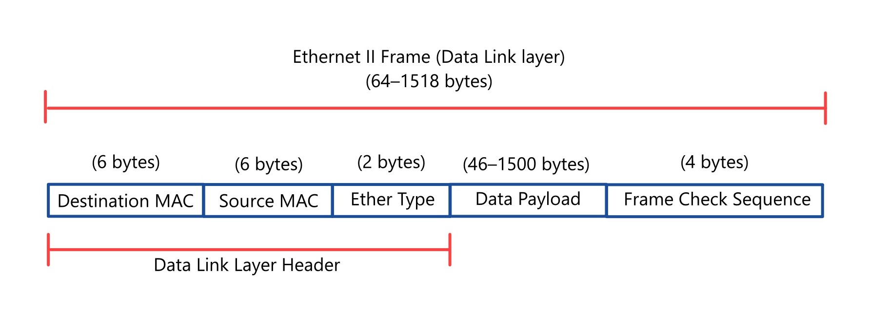
- Destination MAC (6 bytes).
- Source MAC (6 bytes).
- EtherType (2 bytes).
- Payload (Data): 46–1500 bytes.
- Frame Check Sequence (FCS): 4 bytes.
Components of the IEEE Ethernet Frame
The standard Ethernet frame (specifically the Ethernet II frame, commonly used today) includes the following fields:
- Header
- Physical Layer Fields (not part of the data link layer frame):
- Preamble
- Size: 7 bytes
- Purpose: The preamble is a sequence of alternating 1s and 0s (10101010 repeated seven times) used to synchronize the clocks of the sending and receiving devices. It allows the receiver to lock onto the signal before the actual data arrives.
- Details: This field is handled by the physical layer and is typically not included in frame size calculations for higher-layer protocols.
- Start Frame Delimiter (SFD)
- Size: 1 byte
- Purpose: The SFD (10101011) signals the end of the preamble and the beginning of the frame’s meaningful data.
- Details: Like the preamble, it is a physical layer component, bringing the total preamble and SFD size to 8 bytes.
- Preamble
- Data Link Layer Header:
- Destination MAC Address
- Size: 6 bytes
- Purpose: This field specifies the Media Access Control (MAC) address of the intended recipient. A MAC address is a unique 48-bit identifier assigned to a network interface card (NIC).
- Details: It ensures the frame is delivered to the correct device on the LAN. It can be a unicast (single device), multicast (group), or broadcast (all devices) address.
- Source MAC Address
- Size: 6 bytes
- Purpose: This field identifies the MAC address of the sending device.
- Details: This field allows the recipient to identify the sender, enabling two-way communication and supporting protocols that require the sender’s address (e.g., ARP).
- EtherType
- Size: 2 bytes
- Purpose: The EtherType field indicates the protocol encapsulated in the data payload. A protocol identifier indicating the type of data encapsulated in the payload.
- 0x0800 for IPv4
- 0x0806 for ARP
- 0x86DD for IPv6
- Details: In the Ethernet II framing (used widely today), this field is always an EtherType. The EtherType field distinguishes Ethernet II from other Ethernet frame formats (e.g., IEEE 802.3, where this field may indicate payload length instead).
- Destination MAC Address
- Physical Layer Fields (not part of the data link layer frame):
- Data Payload
- Size: 46 to 1500 bytes
- Purpose: This field contains the actual data being transmitted, such as an IP packet, ARP message, or other protocol data unit.
- Details:
- Minimum Size: The payload must be at least 46 bytes to ensure the total frame size (excluding preamble and SFD) is at least 64 bytes, which is necessary for collision detection in traditional Ethernet. If the data is less than 46 bytes, padding bytes are added.
- Maximum Size: The maximum payload is 1500 bytes, defining the Maximum Transmission Unit (MTU) for standard Ethernet.
- Frame Check Sequence (FCS)
- Size: 4 bytes
- Purpose: The FCS is a Cyclic Redundancy Check (CRC) value calculated over the frame (from destination MAC to data payload) to detect transmission errors.
- Details: The sender computes the CRC and appends it to the frame. The receiver recalculates it and compares it to the received FCS; a mismatch indicates an error, and the frame is discarded.
Ethernet II Frame structure (Data link layer)
Ethernet II Packet structure (Physical layer)

Frame Size Summary
- Minimum Frame Size: 64 bytes (excluding preamble and SFD)
- Calculation: 6 (Dest MAC) + 6 (Src MAC) + 2 (EtherType) + 46 (min Payload) + 4 (FCS) = 64 bytes
- Maximum Frame Size: 1518 bytes (excluding preamble and SFD)
- Calculation: 6 + 6 + 2 + 1500 (max Payload) + 4 = 1518 bytes
- Total Transmission Size (on the wire):
- Including preamble (7 bytes) and SFD (1 byte):
- Minimum: 72 bytes (64 + 8)
- Maximum: 1526 bytes (1518 + 8)
- In networking discussions, the frame size typically refers to the 64-to-1518-byte range, excluding physical layer fields.
- Including preamble (7 bytes) and SFD (1 byte):
Additional Notes
- Ethernet II Distinction: The EtherType field is a hallmark of Ethernet II, contrasting with IEEE 802.3 frames, which may use this field for payload length (≤ 1500) rather than protocol type (≥ 1536).
- Physical Layer Fields: The preamble (7 bytes) and SFD (1 byte) are transmitted on the wire but are often excluded from frame size discussions because they are stripped by the physical layer before the frame reaches higher layers.
- Interframe Gap (IFG): After each frame, a small idle period (typically 12 bytes’ worth of time) separates consecutive frames. This is not part of the frame itself but is critical for network timing.
Variations: VLAN-Tagged Frames
In networks using IEEE 802.1Q VLAN tagging, an additional 4-byte field is inserted between the source MAC address and EtherType:
- Tag Protocol Identifier (TPID): 2 bytes (usually 0x8100), identifies the frame as VLAN-tagged.
- Tag Control Information (TCI): 2 bytes, includes the VLAN ID, priority, and other control bits.
- Impact: Increases the frame size by 4 bytes, making the maximum size 1522 bytes (6 + 6 + 4 + 2 + 1500 + 4).
Example Frame Structures
- Standard Ethernet II Frame (Untagged):
| Preamble (7) | SFD (1) | Dest MAC (6) | Src MAC (6) | EtherType (2) | Data (46-1500) | FCS (4) |
Total on wire: 72 to 1526 bytesCommonly cited size: 64 to 1518 bytes (excluding preamble and SFD)
2. VLAN-Tagged Frame:
| Preamble (7) | SFD (1) | Dest MAC (6) | Src MAC (6) | TPID (2) | TCI (2) | EtherType (2) | Data (46-1500) | FCS (4) |
Extensions and Exceptions
- Jumbo Frames: Supported in some modern Ethernet implementations (e.g., Gigabit Ethernet), these allow payloads up to 9000 bytes or more, but they are non-standard.
- Wireless Ethernet (IEEE 802.11): Uses a different frame structure with additional fields, not covered here as the query focuses on IEEE 802.3 wired Ethernet.

Inter Frame Gap (IFG)
The Inter Frame Gap (IFG), also known as the Interpacket Gap (IPG), is a critical component of Ethernet communication, ensuring proper timing and synchronization between transmitted frames.
The Ethernet II inter-frame gap (IFG) is the minimum idle period between the transmission of two consecutive frames in an Ethernet network. Specifically, the IFG is defined as 96 bit times, which refers to the time required to transmit 96 bits at the given network speed.
What is the Inter-Frame Gap?
In Ethernet networks, when a station transmits a frame—such as an Ethernet II frame, which is commonly used to carry IP traffic—it must wait for a short period before sending the next frame. This idle time is the inter-frame gap. The IFG is measured from the end of the Frame Check Sequence (FCS) of one frame to the start of the preamble of the next frame. It is not part of the frame itself but rather a “silence” on the wire between frames.

Duration of the IFG
The IFG is specified as 96 bit times in the IEEE 802.3 standard, which applies to Ethernet networks, including those using the Ethernet II frame format.
- 96 bit times (the time it takes to transmit 96 bits of data).
- Speed-dependent: The actual time in nanoseconds varies with the Ethernet speed:

Thus, the IFG scales with the network speed, maintaining a consistent requirement of 96 bit times regardless of whether the Ethernet operates at 10 Mbps, 100 Mbps, or higher speeds.
Purpose of the IFG
The inter-frame gap serves several key purposes:
- Collision Detection (Half-Duplex Mode): In older half-duplex Ethernet networks, the IFG provides time for stations to detect collisions and ensures that other stations have an opportunity to transmit. This was critical in shared-medium environments like those using hubs.
- Receiver Processing: Even in modern full-duplex Ethernet (e.g., with switches), where collisions do not occur, the IFG allows the receiving device time to process the previous frame before the next one arrives. Switches and NICs use the IFG to process and forward frames without overflow
- Network Timing: The IFG helps maintain proper synchronization and timing across the network.
Key Notes
- Universal Application:
- Applies to all Ethernet variants (Ethernet II, IEEE 802.3, and modern standards like 10GbE).
- Required in both half-duplex and full-duplex modes, though collision detection is irrelevant in full-duplex.
- Minimum Frame Size:
- Ethernet frames must be ≥ 64 bytes (header + payload + FCS) to ensure collision detection.
- IFG is separate: It is not part of the frame itself but a timing gap between frames.
- Jumbo Frames:
- Larger frames (e.g., 9000 bytes) still require the same IFG (96 bit times) between transmissions.
MTU (Maximum Transmission Unit)
The MTU refers to the largest size of the data payload that can be carried in a single frame by a network protocol at a given layer. For Ethernet, the MTU typically refers to the maximum size of the data payload, excluding the Ethernet frame’s overhead (e.g., MAC addresses, EtherType, FCS).
Maximum Data Payload in Ethernet II
For standard Ethernet II frames:
- The maximum data payload size is 1500 bytes.
- This 1500-byte limit is what is commonly referred to as the Ethernet MTU, defining the largest chunk of data that can be transmitted in a single Ethernet frame without requiring fragmentation at the data link layer (Layer 2)
This means that the largest amount of data (e.g., an IP packet) that can be encapsulated in the payload field of a standard Ethernet II frame is 1500 bytes.
The MTU specifically refers to the maximum payload size, which is 1500 bytes in standard Ethernet II. This does not include the Ethernet header (Destination MAC + Source MAC + EtherType = 14 bytes) or the FCS (4 bytes).
The maximum size of the Network Layer 3 IP packet (IP datagram) is tied to MTU of Ethernet Frame.
Practical Example
- Scenario: Sending a 1500-byte IPv4 packet over Ethernet II.
- Payload (MTU): 1500 bytes (IP packet).
- Ethernet Frame Size: 14 (header) + 1500 (payload) + 4 (FCS) = 1518 bytes.
- If the payload were 1000 bytes, the frame size would be 14 + 1000 + 4 = 1018 bytes.
Jumbo Frames (Non-Standard)
Some networks support jumbo frames with larger MTUs (e.g., 9000 bytes), but these are not part of the Ethernet II standard.
Relationship Between Ethernet II MTU and Network Layer IP Packet
The Network Layer (Layer 3), typically implemented by the Internet Protocol (IP), generates IP packets that need to be transported over a physical network. The Ethernet II frame serves as the vehicle for carrying these IP packets across the data link layer. Here’s how the Ethernet II MTU ties to the IP packet:
1. Encapsulation of IP Packet in Ethernet Payload
- The data payload of the Ethernet II frame encapsulates the entire IP packet, which includes:
- IP Header: Typically 20 bytes for IPv4 (without options) or 40 bytes for IPv6.
- IP Payload: The actual data, such as a TCP segment, UDP datagram, or other protocol data.
- The Ethernet II MTU (1500 bytes) represents the maximum size of the IP packet (IP header + IP payload) that can fit into a single Ethernet frame without requiring fragmentation.
For example:
- For an IPv4 packet:
- Maximum IP packet size = Ethernet MTU = 1500 bytes.
- If the IP header is 20 bytes, the maximum IP payload (data) is 1500 – 20 = 1480 bytes.
- For an IPv6 packet:
- If the IP header is 40 bytes, the maximum IP payload is 1500 – 40 = 1460 bytes.
TCP MSS (Maximum Segment Size): In TCP, the Maximum Segment Size is derived from the MTU to avoid fragmentation. For example:
- MSS = MTU – (IP header size + TCP header size).
- For IPv4 with a 20-byte IP header and 20-byte TCP header: MSS = 1500 – (20 + 20) = 1460 bytes.
- TCP ensures that its segments fit within the MTU, preventing IP fragmentation.
Example: IP Packet in an Ethernet II Frame
Consider an IPv4 packet encapsulated in an Ethernet II frame:
- IP Packet: 1480 bytes total (20-byte IP header + 1460-byte TCP segment).
- Ethernet II Frame:
- Destination MAC: 6 bytes
- Source MAC: 6 bytes
- EtherType (0x0800 for IPv4): 2 bytes
- Payload (IP packet): 1480 bytes
- FCS: 4 bytes
- Total frame size (excluding preamble/SFD): 6 + 6 + 2 + 1480 + 4 = 1498 bytes.
- This fits comfortably within the 1500-byte MTU, avoiding fragmentation.
If the IP packet were 2000 bytes, it would exceed the Ethernet MTU, requiring fragmentation (IPv4) or Path MTU Discovery (IPv6).
Key Points Summary
- The Ethernet II MTU (1500 bytes) is the maximum size of the data payload, which typically carries an IP packet (header + data).
- The IP packet must fit within the Ethernet MTU to avoid fragmentation:
- IPv4: Fragmentation is possible but inefficient.
- IPv6: Relies on Path MTU Discovery to avoid fragmentation.
- The MTU influences higher-layer protocols like TCP, which adjusts its MSS to fit within the MTU.
- Proper MTU configuration is critical for efficient network performance, especially in mixed environments or when using jumbo frames.