1. Introduction to UEFI and its Significance
The evolution of computer firmware has been a critical aspect of computing, transitioning from the foundational Basic Input/Output System (BIOS) to the more advanced Unified Extensible Firmware Interface (UEFI). Traditional BIOS represented an older, simpler set of instructions for computer startup, operating in a 16-bit real mode and relying on the Master Boot Record (MBR) for disk partitioning. Its primary function involved initializing core hardware components and then locating and loading the operating system into memory. However, BIOS was inherently limited by its architecture, supporting only up to 2TB drives and a maximum of four primary partitions.
UEFI emerged as a modern, more advanced, and extensible replacement for BIOS, specifically designed to overcome these limitations. A fundamental architectural difference is UEFI’s departure from reliance on fixed boot sectors. Instead, it defines a sophisticated boot manager and utilizes .efi executable files that reside on a dedicated EFI System Partition (ESP). This architectural shift from a fixed, ROM-based system to a more modular, file-based approach is central to UEFI’s enhanced capabilities and adaptability, fundamentally changing the control flow and capabilities of the pre-boot environment. This evolution grants significantly more power and flexibility to the firmware, allowing for advanced diagnostics, network booting, and comprehensive pre-boot environments that were either impossible or highly rudimentary with BIOS. It also implies that the attack surface extends beyond the operating system to the firmware itself, necessitating robust security measures.
Key Advantages of UEFI
UEFI offers several compelling advantages that have driven its widespread adoption in modern computing:
- GUID Partition Table (GPT) Support: UEFI natively supports the GUID Partition Table (GPT), a modern partitioning scheme that overcomes the limitations of MBR. GPT allows for significantly larger disk capacities, extending beyond the 2TB limit, and supports a virtually unlimited number of partitions. This is particularly beneficial for high-capacity storage drives prevalent in modern systems.
- Faster Boot Times: UEFI facilitates faster boot times through optimized initialization processes. Its modular design allows for parallel execution of tasks and more efficient hardware configuration, contributing to a quicker transition from power-on to operating system loading.
- Secure Boot: A critical security feature of UEFI, Secure Boot ensures the integrity and authenticity of the boot process. When enabled, UEFI cryptographically verifies the digital signatures of firmware, bootloader, and operating system components against a trusted database. This mechanism prevents unauthorized or malicious code, such as bootkits and rootkits, from being executed during startup, thereby significantly enhancing system security. This pervasive focus on security indicates that it is no longer an optional feature but a foundational design principle deeply embedded within the UEFI architecture. The reliance on digital signatures, cryptographic verification, and a hierarchy of trust establishes a “root of trust” from the very first moments of system power-on, directly responding to increasingly sophisticated boot-level malware. This architectural decision has profound implications for system integrity and malware prevention, shifting the security baseline significantly higher.
- Graphical User Interface (GUI): Unlike the text-based interface of legacy BIOS, UEFI typically offers a more user-friendly graphical user interface (GUI) for system configuration. This GUI often supports mouse and touchscreen input, making navigation and customization of firmware settings more intuitive and accessible.
- Modular Drivers and Extensibility: UEFI supports modular drivers that can be loaded dynamically during the boot process. This simplifies hardware initialization, allows for easier updates to firmware components, and provides a more extensible platform compared to the monolithic structure of BIOS.
To further illustrate the advancements, a comparison between BIOS and UEFI features is presented below:
| Feature | Legacy BIOS (Basic Input/Output System) | UEFI (Unified Extensible Firmware Interface) |
| Firmware Type | 16-bit, monolithic | 32-bit or 64-bit, modular |
| Disk Partitioning Scheme | Master Boot Record (MBR) | GUID Partition Table (GPT) |
| Maximum Disk Size | 2 TB | 9.4 ZB (effectively unlimited) |
| Maximum Partitions | 4 primary partitions | 128 primary partitions |
| Boot Speed | Slower, sequential initialization | Faster, optimized parallel initialization |
| Security Features | Limited (e.g., boot password) | Secure Boot, Measured Boot, TPM integration |
| User Interface | Text-based (TUI) | Graphical (GUI) with mouse/touch support |
| Driver Support | Limited, relies on Option ROMs | Modular, extensible UEFI drivers |
| Bootloader Location | First sector of boot disk (MBR) | EFI System Partition (ESP) with .efi files |
2. Core UEFI Firmware Boot Phases
The UEFI boot sequence, from the perspective of the firmware itself, is officially divided into three primary, sequential phases: SEC (Security), PEI (Pre-EFI Initialization), and DXE (Driver Execution Environment). Each phase has distinct responsibilities and progressively initializes more of the system, establishing a robust, layered approach to system initialization and trust.

A. SEC (Security) Phase
This is the earliest phase of the UEFI boot process, directly following the CPU’s cold boot entry point. Its fundamental job is to establish a secure and minimal environment necessary to locate, validate, install, and execute the subsequent PEI phase. The CPU begins executing code from a fixed memory address (e.g., 0xFFFFFFF0) mapped to the UEFI Flash Memory, where the SEC phase code resides.
The SEC phase is responsible for handling all platform restart events and creating a temporary memory store, often utilizing the CPU’s cache as SRAM before the main DRAM is available. Crucially, it serves as the “root of trust” in the system by verifying the integrity and authenticity of the PEI phase code. This initial verification is vital, as it ensures that the very first executable code in the boot chain is untampered. Upon successful completion, the SEC phase passes essential handoff information—such as the location and size of temporary memory, stack configuration, and the overall state of the platform—to the PEI Foundation.
B. PEI (Pre-EFI Initialization) Phase
Following the SEC phase, the PEI phase takes control. Its primary role is to configure the entire platform to a state where permanent memory (RAM) is fully initialized and usable, and then to load and execute the DXE phase.
During this phase, the system’s permanent memory (RAM) is initialized, making it available for subsequent stages. The PEI phase describes the memory layout and firmware volume locations using Hand-Off Blocks (HOBs), which are data structures passed to the next phase. It also facilitates communication between various Pre-EFI Initialization Modules (PEIMs) through a mechanism called PPI. Once these critical initializations are complete, control is transferred to the Driver Execution Environment (DXE) phase. The systematic preparation of the core platform by PEI ensures that each subsequent stage operates within an environment that has been validated and incrementally made more capable.
C. DXE (Driver Execution Environment) Phase
The DXE phase is the most extensive and complex part of the UEFI firmware boot. It is responsible for loading and executing UEFI drivers for various configured devices, mounting file systems, and ultimately finding and executing the operating system’s boot code.
During this phase, UEFI services and protocols become fully available, allowing for interaction with devices. UEFI drivers, also known as Option ROMs, are loaded and initialized, enabling the firmware to access hardware components more effectively. This phase prepares the environment for the OS bootloader. The UEFI OS loader, when loaded, uses UEFI services and protocols to access the devices that the firmware exposes, indicating that UEFI acts as a powerful abstraction layer for hardware. This means the operating system’s bootloader and early kernel stages do not need to directly interact with raw hardware registers or specific device quirks; instead, they leverage a standardized set of UEFI-provided interfaces. After the operating system takes control (via the ExitBootServices() call), a portion of the DXE environment, known as DXERuntime, remains resident to handle any OS-to-UEFI calls for runtime services. The persistence of DXERuntime services suggests that UEFI is more than just a pre-boot environment; it is a foundational runtime layer that can provide services to the OS throughout its operation.
3. The Windows UEFI Boot Sequence
The Windows UEFI boot process is a precisely orchestrated sequence of events, characterized by a staged hand-off of control from the low-level firmware to the increasingly complex operating system components.
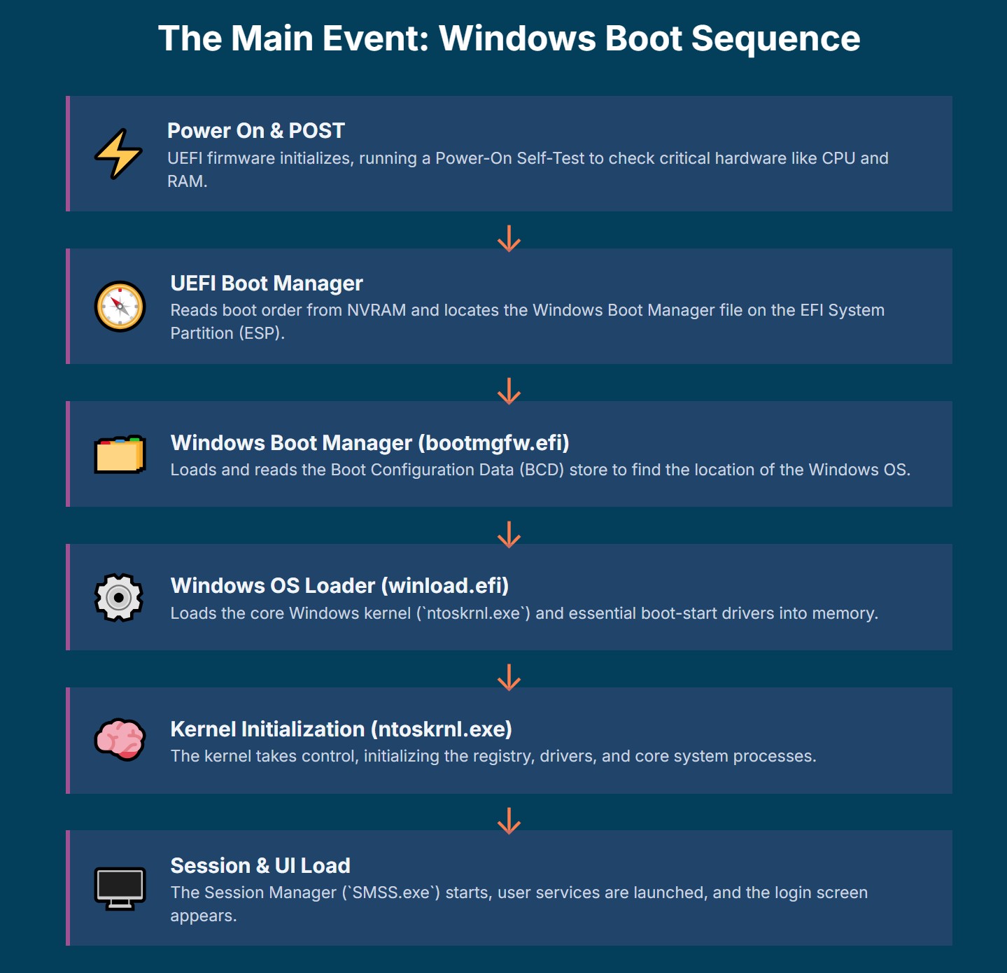
A. PreBoot Phase (Firmware Initialization & POST)
The very first action when a computer is powered on is the execution of the UEFI firmware, which is stored on a small non-volatile storage chip on the motherboard. This firmware immediately initiates the Power-On Self-Test (POST). During POST, the firmware conducts comprehensive hardware checks to ensure all critical components, such as the CPU, RAM, and essential input/output devices, are functioning correctly. It also initializes these hardware components and configures basic system settings. Should any hardware issues be detected during POST, the firmware reports these errors, typically through audible beeps or specific error codes, before proceeding to the next stage.
B. UEFI Boot Manager
Upon successful completion of the PreBoot phase, control is explicitly transferred to the UEFI Boot Manager, which acts as a firmware policy engine. This manager’s first task is to read the boot order list and other configuration details from globally defined NVRAM (Non-Volatile Random Access Memory) variables. These variables contain crucial information, including pointers to specific hardware devices and the exact file paths on those devices where UEFI images, such as operating system boot loaders, are located.
The boot manager systematically scans for available boot entries, which can include various operating systems installed on different disks or partitions, or even network boot options. If multiple bootable options are found or if configured for interactive mode, it can present a graphical menu to the user, allowing them to select the desired operating system or boot entry. The boot manager is also responsible for processing any necessary UEFI “Driver load option entries” before “Boot load option entries”.
C. Windows Boot Manager (bootmgfw.efi)
Once the UEFI Boot Manager identifies and selects the Windows boot entry, it proceeds to load the Windows Boot Manager, specifically the bootmgfw.efi file. This crucial executable file resides within the EFI System Partition (ESP), a dedicated FAT32 partition on the storage device. The ESP serves as a repository for UEFI applications, including operating system boot loaders, and other files necessary for these applications to run. This design allows the UEFI firmware to directly access and execute bootloaders as files, making the boot process more flexible and robust. It centralizes all necessary boot components in a standardized, accessible location, which simplifies multi-booting scenarios and makes bootloader updates or repairs significantly easier compared to the rigid MBR structure.
bootmgfw.efi is the designated Windows boot manager for UEFI-based systems, loaded directly by the UEFI firmware. It operates within the firmware’s already established execution context, meaning that fundamental system structures like the Global Descriptor Table (GDT), Interrupt Descriptor Table (IDT), stack, and page tables have been initialized by the UEFI firmware. The firmware also ensures an identity mapping of physical memory, providing a consistent memory environment for bootmgfw.efi to operate within. A primary and critical responsibility of bootmgfw.efi is to load and interpret the Boot Configuration Data (BCD) store. The BCD store is a vital database that replaced the older
boot.ini file used in legacy BIOS systems. It contains all the configuration information necessary to boot Windows, with each boot application or operating system entry represented by a unique BCD object, typically identified by GUIDs. This store dictates boot options, recovery environments, and other critical boot parameters.
D. Windows OS Loader (winload.efi)
After bootmgfw.efi successfully processes the BCD store and determines the correct boot entry, it loads the Windows OS Loader, which is the winload.efi executable. This component is pivotal in preparing the environment for the Windows kernel.
winload.efi is primarily responsible for identifying and loading the critical “boot start” drivers required to initialize the Windows kernel. These drivers are essential because they enable the kernel to directly access the disk and other crucial hardware components on its own, without relying on the generic firmware-provided functions, such as UEFI’s Block I/O Protocol. This includes various categories of drivers, such as core drivers, temporary core drivers, and Early Launch Anti-Malware (ELAM) drivers. It also loads CPU-specific microcode updates ( mcupdate_[OsArch].dll) to ensure optimal processor functionality. The process involves checking dependencies and API set dependencies for each driver. Concurrently with the driver loading process, winload.efi loads the system registry hive into memory. This hive contains critical configuration data for the operating system, including details about devices, services, and the boot-start drivers themselves.
E. Windows NT OS Kernel (ntoskrnl.exe) Initialization
Once the essential drivers and the system hive are loaded into memory and the necessary memory structures are established by winload.efi, the core Windows NT OS Kernel, ntoskrnl.exe, is loaded into memory.
At this point, winload.efi passes full control to the kernel, marking the critical transition from the bootloader phase to the kernel initialization phase. The kernel then proceeds to pick up additional Registry settings and load further drivers required for full system functionality. It initializes core operating system components, sets up memory management, process scheduling, and establishes the hardware abstraction layer. The kernel continues to initialize device drivers to enable communication with all hardware components and establishes the root filesystem, mounting it for access. This layered and progressive hand-off architecture ensures both stability and efficiency. By the time the Windows kernel takes full control, it operates within a fully initialized and optimized environment tailored specifically for Windows, minimizing the need for the OS to re-initialize hardware or rely on firmware services for basic operations. This optimized transition contributes to faster boot times and a more stable system, as each component is responsible for a specific set of tasks before passing control to a more specialized component.
F. Session Initialization (SMSS.exe, Csrss.exe) and User Interface Loading
Following the kernel’s initializations, control is transferred to the system manager process. For Windows, this involves the Session Manager Subsystem (
SMSS.exe). SMSS.exe is the first user-space program executed by the kernel. It is responsible for managing system initialization, launching essential services and processes required for the operating system to function, and preparing the environment for user processes. This includes starting the Client/Server Runtime Subsystem (
Csrss.exe). User-space applications and services are then initialized based on configuration files, setting up user environments and ensuring background services are running as needed. Finally, the graphical user interface (UI) is loaded, and the Windows login screen is presented to the user, signaling the completion of the core boot process.
The following table summarizes the stages and key files involved in the Windows UEFI boot process:
| Stage | Key Component/File | Primary Function |
| PreBoot | UEFI Firmware, POST | Initializes basic hardware, performs Power-On Self-Test, establishes temporary memory, verifies PEI. |
| UEFI Boot Manager | Firmware Policy Engine | Reads NVRAM boot order, scans for boot entries, presents boot menu (if applicable), loads bootmgfw.efi. |
| Windows Boot Manager | bootmgfw.efi (on ESP) | Loaded by UEFI firmware, loads and interprets Boot Configuration Data (BCD) store, prepares environment for OS loader. |
| Windows OS Loader | winload.efi | Loads critical “boot start” drivers (including ELAM), loads system registry hive, loads ntoskrnl.exe. |
| Windows NT OS Kernel | ntoskrnl.exe | Initializes core OS components, sets up memory management, process scheduling, loads additional drivers, establishes root filesystem. |
| Session Initialization | SMSS.exe, Csrss.exe | Manages system initialization, launches essential services, prepares user environment, loads UI. |
4. Hardware Components Involvement in the Boot Process
The UEFI boot process is a complex interplay between software and various hardware components, each playing a crucial role from the moment power is applied until the operating system takes full control.
A. CPU (Central Processing Unit)
The CPU is the very first component to become active upon power-on. It begins executing code from a fixed, predetermined address, which points to the UEFI firmware stored in a non-volatile memory chip (e.g., SPI flash) on the motherboard. This initial code is often memory-mapped, allowing the CPU to fetch instructions directly. Throughout the SEC, PEI, and DXE phases of the UEFI firmware, the CPU is continuously active, fetching, decoding, and executing instructions to initialize itself, the RAM, the chipset, and other critical components. Subsequently, as the Windows bootloaders ( bootmgfw.efi, winload.efi) and the OS kernel (ntoskrnl.exe) are loaded into RAM, the CPU processes their instructions, orchestrating the entire boot sequence. During the winload.efi phase, the CPU’s functionality is further optimized by loading CPU-specific microcode updates, ensuring compatibility and performance.
B. RAM (Random Access Memory)
In the earliest SEC phase, a temporary memory store is established, often utilizing the CPU’s cache, to facilitate initial operations before the main system RAM is fully initialized. A core responsibility of the PEI phase is the comprehensive initialization of the system’s permanent memory (RAM). This involves configuring memory controllers and modules, and describing the available memory in Hand-Off Blocks (HOBs) for subsequent phases. Once RAM is initialized and stable, it becomes the primary workspace for the boot process. All critical software components, including the UEFI Boot Manager, Windows Boot Manager ( bootmgfw.efi), Windows OS Loader (winload.efi), and the Windows NT OS Kernel (ntoskrnl.exe), are loaded into RAM for execution. The system registry hive, containing vital OS configuration data, is also loaded into memory by winload.efi.
C. Storage Devices (HDD/SSD)
Modern systems utilizing UEFI employ the GUID Partition Table (GPT) for disk partitioning, which allows for significantly larger storage capacities and more partitions compared to the legacy MBR. The EFI System Partition (ESP) is a dedicated FAT32 partition on the storage device that is central to the UEFI boot process. It serves as a repository for UEFI applications, including operating system bootloaders ( bootmgfw.efi), and other files necessary for these applications to run. The UEFI Boot Manager reads the boot order from NVRAM variables, which include pointers to the specific hardware device and the UEFI image file (e.g., bootmgfw.efi) located on that device. Subsequently, the OS bootloader and kernel files are read from the storage device and loaded into RAM for execution.
D. Graphics Card/Integrated Graphics
While not extensively detailed in all available information, the UEFI specification includes the Graphics Output Protocol (GOP). This protocol allows the UEFI firmware to provide high-resolution graphical output during the pre-boot environment. This capability is essential for displaying the graphical UEFI settings interface and any boot menus presented by the UEFI Boot Manager. As the Windows OS Loader ( winload.efi) takes over, it loads essential drivers, which would include generic or basic graphics drivers. These drivers enable proper display functionality as the operating system loads and transitions to its own graphics subsystem. The UEFI OS loader uses UEFI services and protocols to access the devices that the firmware exposes. This indicates a significant level of hardware abstraction provided by UEFI, where the operating system’s bootloader does not need to directly manage complex hardware registers or specific device quirks during the early boot stages. Instead, it interacts with a standardized set of UEFI-provided services. This standardization simplifies operating system development and ensures broader hardware compatibility.
E. Trusted Platform Module (TPM)
The Trusted Platform Module (TPM) 2.0 is a dedicated cryptographic processor that is a mandatory hardware requirement for Windows 11. It provides hardware-rooted security functions, including secure storage of cryptographic keys, platform integrity measurements, and cryptographic operations. Most modern processors include a built-in secure element that supports the TPM 2.0 specification (e.g., Intel Platform Trust Technology (PTT) on Intel CPUs, or Firmware TPM (fTPM) on AMD CPUs). These features often need to be explicitly enabled within the UEFI menu settings to function. TPM plays a crucial role in the Secure Boot process by helping to verify the integrity of the boot chain and protecting sensitive data. The explicit and mandatory requirement for TPM 2.0 in conjunction with UEFI and Secure Boot reveals a deep hardware-software co-dependency for achieving comprehensive system security. Secure Boot primarily verifies the software components’ digital signatures, ensuring that only trusted code executes. However, TPM provides a hardware-rooted secure environment for cryptographic operations, key storage, and integrity measurements. This means that even if a software vulnerability were to be exploited, the TPM could prevent tampering with the boot process or securely store sensitive data, creating a robust, multi-layered defense. This integrated approach signifies a move towards a “measured boot” environment where hardware actively participates in validating the integrity of the entire software stack from the earliest stages.
F. Motherboard Firmware (NV-RAM)
The UEFI firmware code itself is stored on a small, non-volatile storage chip directly integrated onto the motherboard. This allows the firmware to persist even when the system is powered off. Crucial UEFI settings, including the boot order list, are stored in global NVRAM (Non-Volatile Random Access Memory) variables within the firmware. Furthermore, the essential Secure Boot databases—the signature database ( db), the revoked signatures database (dbx), and the Key Enrollment Key database (KEK)—are securely stored in the firmware’s NV-RAM during the manufacturing process. These databases are fundamental for the Secure Boot process to function correctly.
5. Key Security Features: Secure Boot
Secure Boot is a cornerstone of UEFI’s security model, designed to protect the integrity of the boot process from its very inception.
Digital Signature Verification Process
Secure Boot is a fundamental security feature within UEFI that ensures the integrity and authenticity of the boot process from the moment the computer is powered on. When Secure Boot is enabled, the UEFI firmware rigorously checks the digital signatures of every piece of boot software before allowing it to execute. This includes UEFI firmware drivers (often referred to as Option ROMs), EFI applications (such as the operating system bootloader), and the operating system components themselves. The firmware verifies that these components are digitally signed by a trusted authority and that their signatures are intact and haven’t been modified. If the signatures are valid, the PC proceeds with the boot process; if verification fails, the firmware halts the boot process, initiates remediation, or prevents the unauthorized code from executing, thereby protecting against bootkits, rootkits, and other forms of malware.
Secure Boot Databases (db, dbx, KEK) and Platform Key (PK)
The trust mechanism of Secure Boot relies on a set of cryptographic databases stored securely in the firmware’s nonvolatile RAM (NV-RAM) at the time of manufacturing. These databases are provisioned by the OEM. The db (Signature Database) contains the digital signatures or image hashes of UEFI applications, operating system loaders (such as the Microsoft Operating System Loader or Boot Manager), and UEFI drivers that are explicitly authorized and permitted to load on the device. Conversely, the dbx (Revoked Signatures Database) lists the hashes of blacklisted or revoked software components that are explicitly forbidden from loading, allowing for blocking known malicious or vulnerable boot components. The KEK (Key Enrollment Key Database) contains public keys used to securely update the db and dbx databases, ensuring that only authorized entities can modify the list of trusted or untrusted boot components.
After these databases have been added and the final firmware validation and testing are complete, the OEM generates a Platform Key (PK). The PK is the root of trust for the entire platform; it is used to sign the KEK database and ensures that the firmware itself is locked from unauthorized editing, allowing only updates signed with the correct key or updates by a physically present user through firmware menus. The process described, where OEMs are responsible for creating, storing, and provisioning these keys and databases, highlights a critical dependency. The initial trust anchor for Secure Boot is not established by the user or the operating system, but by the hardware manufacturer. This means the foundational security of the entire boot chain is inherently tied to the OEM’s adherence to secure manufacturing practices and key management.
Protection Against Malware and Rollback
Secure Boot’s primary objective is to protect the system against unauthorized software, including sophisticated bootkits and rootkits, by ensuring that only trusted and signed code can execute during the boot process. Beyond preventing malicious code, the UEFI system also incorporates mechanisms to protect against the rollback of firmware to older, potentially vulnerable versions. This “rollback protection” ensures that attackers cannot downgrade the firmware to exploit known weaknesses.
In the event of a problem with the Windows Boot Manager, the firmware is designed to attempt booting a backup copy. If this also fails, the firmware must initiate OEM-specific remediation. Furthermore, if issues arise with drivers or the NTOS kernel after the Windows Boot Manager has successfully started, the system automatically loads the Windows Recovery Environment (Windows RE) to facilitate recovery and repair of these components. The inclusion of features like rollback protection and the sophisticated recovery mechanisms demonstrates a highly evolved and multi-layered approach to boot security and resilience. This is not merely about preventing unauthorized code but also about ensuring system robustness and recoverability from various boot failures. The integration between firmware-level recovery and OS-level recovery shows a cohesive strategy for maintaining system availability.
6. Important Details for Users
Understanding the UEFI boot process provides users with valuable knowledge for system management, configuration, and troubleshooting.
Accessing UEFI Settings and Configuration Options
To access the UEFI settings interface (often still colloquially referred to as “BIOS settings”), users typically need to press a specific key or key combination during the computer’s initial startup process. Common keys include Del, F2, F10, or Esc, though the exact key can vary depending on the computer manufacturer and model. The UEFI settings provide a comprehensive graphical interface (GUI) for configuring various aspects of the computer’s firmware and hardware. Within this interface, users can modify critical boot options, set the boot order for different devices (e.g., hard drive, SSD, USB, network), enable or disable Secure Boot, adjust system clock settings, manage hardware components, and even update the UEFI firmware itself. While Secure Boot imposes stringent security measures, the ability for users to easily access UEFI settings, modify boot options, and even disable Secure Boot if needed indicates that UEFI provides a crucial balance between robust security and user control. This flexibility is vital for advanced users or IT professionals who may need to install alternative operating systems, perform low-level diagnostics, or manage hardware configurations that could otherwise be restricted by default secure settings.
Multi-Operating System Support
A significant advantage of UEFI over legacy BIOS is its robust support for installing and managing multiple operating systems on the same computer. Each operating system can have its own dedicated bootloader, typically residing as an .efi file on the EFI System Partition (ESP). The UEFI Boot Manager is designed to recognize these multiple bootloaders and presents a menu to the user, allowing them to choose which operating system or boot entry to load during the startup process. This functionality seamlessly enables dual-boot or multi-boot setups, providing users with flexibility.
Troubleshooting Common UEFI Boot Issues (Windows Recovery Environment)
UEFI systems, particularly when running Windows, incorporate advanced recovery mechanisms. If a problem occurs with the Windows Boot Manager (bootmgfw.efi), the UEFI firmware is designed to attempt booting a backup copy of the Windows Boot Manager, enhancing resilience. Furthermore, if issues arise with essential drivers or the Windows NT OS Kernel ( ntoskrnl.exe) after the Windows Boot Manager has successfully initiated, the system is configured to automatically load the Windows Recovery Environment (Windows RE). Windows RE provides a suite of tools for troubleshooting, repairing, or recovering the operating system without requiring external installation media. The fact that the UEFI firmware can initiate OEM-specific remediation or directly load Windows RE when boot failures occur demonstrates a sophisticated and tightly integrated recovery strategy between the firmware and the operating system. This integrated approach significantly improves system resilience and reduces potential downtime for users.
7. Hardware Requirements for Windows in UEFI Mode
Modern Windows operating systems, particularly Windows 11, have stringent hardware requirements that mandate the use of UEFI mode to leverage its advanced security and functionality features.
Minimum Requirements for Windows 11 (UEFI Mode)
To install or upgrade to Windows 11, devices must meet the following minimum hardware requirements:
- Processor: A processor with a clock speed of 1 gigahertz (GHz) or faster, featuring two or more cores, on a compatible 64-bit processor or System on a Chip (SoC). This ensures sufficient processing power for the operating system.
- Memory (RAM): A minimum of 4 gigabytes (GB) of RAM is required for basic operation. More RAM is generally recommended for optimal performance and multitasking.
- Storage: A storage device (HDD or SSD) with 64 GB or greater available disk space is necessary for the operating system installation. Additional storage may be required over time for updates and to enable specific features within the OS.
- Graphics Card: The graphics card must be compatible with DirectX 12 or later and utilize a WDDM 2.0 driver. This ensures modern graphical capabilities and efficient rendering.
- Display: A high-definition (720p) display, measuring 9 inches or greater diagonally, with 8 bits per color channel, is specified for visual output.
- Internet Connection: An internet connection is necessary to perform updates, download, and utilize certain features of Windows. Specifically, the Windows 11 Home edition requires an internet connection and a Microsoft Account to complete the initial device setup.
- Microsoft Account: Required for initial setup of Windows 11 Home edition.
Specific UEFI-related Requirements
Beyond the general minimums, Windows 11 imposes specific requirements tied directly to the UEFI architecture:
- System Firmware: The system firmware must be UEFI and explicitly capable of Secure Boot. For Windows 11, running with UEFI is a strict requirement, and it is not compatible with legacy BIOS or Compatibility Support Module (CSM) modes. This strict and mandatory nature of UEFI and Secure Boot for Windows 11 is a deliberate strategic decision by Microsoft. By explicitly dropping compatibility with legacy BIOS, Microsoft is actively steering the entire PC ecosystem towards a higher, more uniform baseline for system security and hardware modernity. This policy decision forces hardware manufacturers and users to adopt more secure and advanced technologies, significantly enhancing the overall security posture of the Windows platform.
- TPM (Trusted Platform Module): A Trusted Platform Module (TPM) version 2.0 is a mandatory hardware requirement for Windows 11. Most modern processors integrate a secure element that supports the TPM 2.0 specification (e.g., Intel’s Platform Trust Technology (PTT) or AMD’s Firmware TPM (fTPM)). These features often need to be enabled within the UEFI menu settings before the system can successfully boot Windows 11.
End