The Transmission Control Protocol (TCP), as specified in RFC 9293 (August 2022), is a core protocol of the Internet Protocol Suite, operating at the transport layer. It provides reliable, ordered, and error-checked delivery of data between applications over an IP network. TCP is widely used in applications requiring guaranteed delivery, such as web browsing (HTTP/HTTPS), email (SMTP/IMAP), and file transfers (FTP).
TCP Key Concepts
TCP’s design ensures reliable communication in diverse and potentially unreliable network environments. The following key concepts underpin its functionality:
1. Connection-Oriented Communication
- Description: TCP establishes a virtual connection between two endpoints (client and server) before data transfer begins. This connection is maintained until explicitly closed.
- Mechanism: The three-way handshake (SYN, SYN-ACK, ACK) initializes the connection, ensuring both sides agree on sequence numbers and are ready to communicate.
- Purpose: Guarantees that both endpoints are synchronized and prepared for reliable data exchange.
2. Reliable Data Transfer
- Description: TCP ensures that all data sent is received correctly, in order, and without duplication.
- Mechanisms:
- Sequence Numbers: Each byte of data is assigned a sequence number, allowing the receiver to reorder segments and detect missing data.
- Acknowledgments (ACKs): The receiver sends ACKs to confirm receipt of data, specifying the next expected byte.
- Retransmission: If a segment is lost or corrupted (detected via timeouts or missing ACKs), the sender retransmits it.
- Checksum: A checksum in the TCP header verifies data integrity.
- Purpose: Ensures no data is lost or corrupted during transmission.
3. Flow Control
- Description: TCP prevents a fast sender from overwhelming a slower receiver.
- Mechanism: The Window Size field in the TCP header advertises the receiver’s available buffer space (receive window). The sender adjusts its transmission rate to stay within this window.
- Purpose: Avoids buffer overflow and ensures efficient data transfer.
4. Congestion Control
- Description: TCP adapts to network congestion to prevent packet loss and maintain network stability.
- Mechanisms:
- Congestion Window: The sender maintains a congestion window, limiting the amount of unacknowledged data in flight.
- Algorithms: TCP uses algorithms like Slow Start, Congestion Avoidance, Fast Retransmit, and Fast Recovery to adjust the congestion window based on network conditions.
- Explicit Congestion Notification (ECN): Allows routers to signal congestion without dropping packets, using the CWR and ECE flags.
- Purpose: Balances performance with network resource constraints.
5. Ordered Data Delivery
- Description: TCP ensures that data is delivered to the application in the same order it was sent.
- Mechanism: Sequence numbers allow the receiver to reorder out-of-sequence segments before passing them to the application.
- Purpose: Critical for applications like file transfers or web pages, where data order matters.
6. Error Detection
- Description: TCP detects errors in transmitted data.
- Mechanism: The Checksum field in the TCP header is computed over the TCP segment, pseudo-header, and data. If the checksum fails, the segment is discarded, triggering retransmission.
- Purpose: Ensures data integrity.
7. Connection Termination
- Description: TCP provides a graceful mechanism to close connections.
- Mechanism: The four-way handshake (FIN, ACK, FIN, ACK) allows both sides to signal they have no more data to send and confirm closure.
- Purpose: Ensures all data is delivered before the connection is terminated.
8. Full-Duplex Communication
- Description: TCP supports simultaneous bidirectional data transfer.
- Mechanism: Each endpoint maintains separate sequence numbers and windows for sending and receiving, allowing data to flow in both directions concurrently.
- Purpose: Enables efficient, interactive communication (e.g., in client-server applications).
9. State Management
- Description: TCP maintains a state machine to track the connection’s lifecycle.
- States: Includes CLOSED, LISTEN, SYN-SENT, SYN-RECEIVED, ESTABLISHED, FIN-WAIT, CLOSE-WAIT, LAST-ACK, and others.
- Purpose: Ensures proper handling of connection setup, data transfer, and termination.
TCP Header Format
The TCP header encapsulates control information for managing connections and data transfer. It is typically 20 bytes long (without options) and is included in every TCP segment. Below is a detailed breakdown of the TCP header fields, their sizes, and their uses.
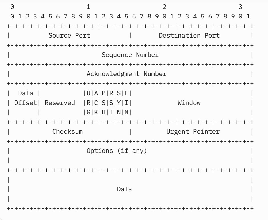
TCP Header Fields
- Source Port (16 bits)
- Purpose: Identifies the sending application’s port number.
- Use: Allows the receiver to direct the segment to the correct application or process. Combined with the source IP address, it uniquely identifies the sender’s endpoint.
- Example: A web client might use an ephemeral port (e.g., 49152) as the source port when connecting to a server.
- Destination Port (16 bits)
- Purpose: Identifies the receiving application’s port number.
- Use: Specifies the target application on the destination host. Common ports include 80 (HTTP), 443 (HTTPS), or 22 (SSH).
- Example: A client connecting to a web server sets the destination port to 80 or 443.
- Sequence Number (32 bits)
- Purpose: Tracks the position of the segment’s data in the sender’s byte stream.
- Use:
- If SYN=1, the Sequence Number is the Initial Sequence Number (ISN).
- If SYN=0, it is the sequence number of the first byte of data in the segment.
- Enables the receiver to reorder segments and detect missing or duplicated data.
- Example: For a segment carrying bytes 1001–2000, the Sequence Number is 1001.
- Acknowledgment Number (32 bits)
- Purpose: Indicates the next byte the receiver expects, confirming receipt of all prior bytes.
- Use:
- Valid only when ACK=1.
- Drives TCP’s reliability by acknowledging successful receipt of data.
- Supports cumulative acknowledgments (e.g., Ack=2001 confirms bytes up to 2000).
- Example: If the receiver has received bytes up to 2000, it sets Ack=2001.
- Data Offset (4 bits)
- Purpose: Specifies the length of the TCP header in 32-bit words (including options).
- Use:
- Indicates where the data begins in the segment.
- Minimum value is 5 (20 bytes, no options); maximum is 15 (60 bytes, with 40 bytes of options).
- Example: A header with 24 bytes (20 bytes + 4 bytes of options) has Data Offset=6.
- Reserved (4 bits)
- Purpose: Reserved for future use.
- Use: Must be set to 0 by the sender and ignored by the receiver.
- Note: Previously 6 bits, reduced to 4 in RFC 9293 to accommodate additional control bits.
- Control Bits (8 bits)
- Purpose: Flags that control TCP’s behavior for the segment.
- Flags (from MSB to LSB):
- CWR (Congestion Window Reduced): Set by the sender to indicate it has reduced its congestion window in response to congestion (used with ECN).
- ECE (ECN-Echo): Set by the receiver to signal congestion (ECN) or negotiate ECN support during connection setup.
- URG (Urgent): Indicates urgent data; the Urgent Pointer field is valid.
- ACK (Acknowledgment): Indicates the Acknowledgment Number is valid.
- PSH (Push): Requests immediate delivery of data to the application without buffering.
- RST (Reset): Signals an error or abrupt connection termination.
- SYN (Synchronize): Initiates a connection and synchronizes sequence numbers.
- FIN (Finish): Indicates the sender has no more data to send, requesting connection closure.
- Use:
- Manages connection setup (SYN, ACK), data transfer (ACK, PSH, URG), termination (FIN, ACK), error handling (RST), and congestion control (CWR, ECE).
- Example combinations: SYN for connection start, FIN+ACK for termination, RST for errors.
- Window (16 bits)
- Purpose: Advertises the receiver’s available buffer space (receive window).
- Use:
- Controls flow by limiting how much unacknowledged data the sender can transmit.
- A window of 0 halts transmission until the receiver advertises a non-zero window.
- Supports window scaling (via options) for larger windows in high-bandwidth networks.
- Example: A Window=65535 means the receiver can accept 65,535 bytes.
- Checksum (16 bits)
- Purpose: Verifies the integrity of the TCP segment.
- Use:
- Computed over the TCP header, data, and a pseudo-header (including IP addresses, protocol, and segment length).
- The receiver discards segments with invalid checksums, triggering retransmission.
- Example: Ensures data wasn’t corrupted during transmission.
- Urgent Pointer (16 bits)
- Purpose: Indicates the offset from the Sequence Number where urgent data ends.
- Use:
- Valid only when URG=1.
- Points to the last byte of urgent data, which the receiver should prioritize.
- Rarely used in modern applications (e.g., Telnet for interrupts).
- Example: If Sequence Number=1001 and Urgent Pointer=10, urgent data spans bytes 1001–1010.
- Options (0–40 bytes, variable length)
- Purpose: Provides additional functionality or parameters.
- Use:
- Padded to ensure the header length is a multiple of 32 bits.
- Common options include:
- Maximum Segment Size (MSS): Specifies the maximum segment size (excluding headers) during connection setup.
- Window Scaling: Extends the Window field for high-bandwidth networks.
- Timestamps: Improves round-trip time estimation and protects against wrapped sequence numbers.
- Selective Acknowledgments (SACK): Allows acknowledgment of non-contiguous data blocks.
- Example: An MSS option might specify 1460 bytes to match the network’s MTU.
- Padding (variable, if needed)
- Purpose: Ensures the header length is a multiple of 32 bits.
- Use: Consists of zeros to align the data field.
- Example: If the header is 22 bytes, 2 bytes of padding are added to reach 24 bytes.
TCP Header Size
- Minimum: 20 bytes (no options, Data Offset=5).
- Maximum: 60 bytes (with 40 bytes of options, Data Offset=15).
- Typical: 20–32 bytes, depending on options like MSS, Window Scaling, or Timestamps.
TCP Header: Source Port Field
The Source Port field in the TCP (Transmission Control Protocol) header, is a critical component that identifies the sending application’s port number. This field plays an essential role in enabling communication between applications over a TCP connection.
Overview of the Source Port Field
- Size: 16 bits (2 bytes).
- Location: The first field in the TCP header, occupying bits 0–15.
- Purpose: Specifies the port number of the application or process on the sending device, allowing the receiver to identify the source of the TCP segment.
- Role in Communication: Together with the source IP address, destination IP address, and destination port, the Source Port uniquely identifies a TCP connection (forming a “socket pair”).
- Value Range: 0 to 65,535 (since it’s a 16-bit field).
- 0: Reserved and not typically used for active connections, though it may appear in specific cases (e.g., some implementations for diagnostic purposes).
- 1–1023: Well-known ports, typically reserved for system services (e.g., 80 for HTTP, 443 for HTTPS), though rarely used as source ports.
- 1024–49151: Registered ports, often used for client applications or services.
- 49152–65535: Ephemeral (or dynamic) ports, commonly used by clients for temporary connections.
Purpose of the Source Port
The Source Port field serves the following primary purposes in TCP communication:
- Identify the Sending Application:
- The Source Port specifies which application or process on the sending device initiated the TCP segment. This allows the receiving device to send responses back to the correct application.
- Enable Multiplexing:
- Multiple applications on the same device can use TCP simultaneously. The Source Port, combined with the Destination Port, differentiates these connections, even if they share the same IP address.
- Uniquely Identify a TCP Connection:
- A TCP connection is uniquely identified by the 4-tuple: (Source IP, Source Port, Destination IP, Destination Port). The Source Port is a critical part of this tuple, ensuring that each connection is distinct.
- Support Bidirectional Communication:
- In full-duplex TCP connections, the Source Port in one direction becomes the Destination Port in the reverse direction, enabling seamless two-way communication.
Uses of the Source Port in TCP Communication
The Source Port field plays a pivotal role in TCP communication. The Source Port is used throughout the TCP connection lifecycle, from establishment to termination. Here’s a detailed look at its uses:
1. Identifying the Sending Application
- Function: The Source Port number uniquely identifies the application or process on the sending host that initiated the TCP segment.
- Example: If a web browser on a client device initiates a connection to a web server, the browser selects a Source Port number (e.g., 49152) to represent its process. This number is included in the TCP header of the outgoing segment.
- Significance: The receiving host (e.g., the web server) uses this Source Port number when crafting a response, ensuring the reply reaches the correct application (the browser) on the sender’s device.
2. Connection Establishment (Three-Way Handshake)
- Role: The Source Port identifies the client application initiating the connection.
- Usage:
- When a client starts a TCP connection (e.g., a web browser connecting to a server), it selects a Source Port, typically an ephemeral port (49152–65535), assigned by the operating system.
- The client sends a SYN segment with the Source Port set to this value and the Destination Port set to the server’s well-known port (e.g., 443 for HTTPS).
- The server uses the Source Port from the client’s SYN segment to address its SYN-ACK response, ensuring the response reaches the correct client application. The server uses the Source Port from the client’s SYN segment to address its SYN-ACK response, ensuring the response reaches the correct client application.
- The client completes the handshake with an ACK segment, maintaining the same port assignments.
- Example:
- Client (IP: 192.168.1.10, Source Port: 49152) → Server (IP: 93.184.216.34, Destination Port: 443) SYN, Source Port=49152, Destination Port=443
- Server → Client: SYN-ACK, Source Port=443, Destination Port=49152
- Client → Server: ACK, Source Port=49152, Destination Port=443
- Significance: The Source Port ensures the server can respond to the correct client process, even if multiple clients on the same device are connecting to the same server.
3. Data Transfer
- Role: Maintains connection identity during data exchange.
- Usage:
- In every TCP segment sent during the connection (data segments, ACKs, etc.), the Source Port remains constant, identifying the sending application.
- The receiver uses the Source Port to demultiplex incoming segments, directing them to the appropriate application or socket.
- For example, a web browser with multiple open tabs may use different Source Ports for each tab’s connection to the same web server, allowing the operating system to route responses correctly.
- Example:
- A client downloading a file sends data segments with Source Port=49153 and Destination Port=21 (FTP). The server’s responses use Source Port=21 and Destination Port=49153.
- Significance: Ensures that data and ACKs are associated with the correct connection, supporting multiplexing and reliable delivery.
4. Connection Termination (Four-Way Handshake)
- Role: Identifies the application closing the connection.
- Usage:
- During connection termination, FIN segments include the same Source Port used throughout the connection to maintain continuity.
- The receiver uses the Source Port to send ACKs or its own FIN, ensuring the closure process is tied to the correct socket.
- Example:
- Client → Server: FIN, Source Port=49152, Destination Port=443
- Server → Client: ACK, Source Port=443, Destination Port=49152
- Significance: Maintains connection identity during graceful closure.
5. Error Handling
- Role: Identifies the source of error-related segments.
- Usage:
- If a server sends a RST (Reset) segment to terminate a connection (e.g., due to an invalid port or closed socket), it uses the client’s Source Port as the Destination Port in the RST segment.
- The client uses the Source Port to associate the RST with the correct connection.
- Example:
- Client → Server: Source Port=49152, Destination Port=9999 (closed port)
- Server → Client: RST, Source Port=9999, Destination Port=49152
- Significance: Ensures error messages are delivered to the correct application.
6. Facilitating Two-Way Communication
- Function: TCP is a bidirectional protocol, meaning both hosts send and receive data. The Source Port in an outgoing segment becomes the Destination Port in the response segment.
- Process:
- When a client sends a TCP segment to a server, the client’s Source Port (e.g., 49152) and the server’s Destination Port (e.g., 80 for HTTP) are specified.
- The server responds with a TCP segment where the Source Port is 80 (the server’s port) and the Destination Port is 49152 (the client’s original Source Port).
- Significance: This swapping of port numbers ensures that responses are routed back to the correct process on the original sender.
Additional Uses and Considerations
- Ephemeral Port Selection:
- Mechanism: Clients typically use ephemeral ports (49152–65535) as Source Ports, dynamically assigned by the operating system. This avoids conflicts with well-known or registered ports used by servers.
- Use: Ensures multiple simultaneous connections from the same device are uniquely identified.
- Example: When you open multiple tabs in a web browser, each tab may establish a separate TCP connection to the same web server, each using a different Source Port (e.g., 49152, 49153, 49154) to differentiate the connections.
- Constraint: The limited range of ephemeral ports (approximately 16,384) can lead to port exhaustion in high-connection scenarios (e.g., NAT devices or busy clients). Modern systems mitigate this with larger ephemeral port ranges or reuse policies.
- Network Address Translation (NAT):
- Role: In NAT environments, the Source Port is often rewritten to allow multiple devices behind a NAT to share a single public IP address.
- Usage: The NAT device maps the private IP and Source Port to a public IP and a new Source Port, maintaining a mapping table to route responses correctly.
- Example:
- Private client (192.168.1.10:49152) → NAT maps to (203.0.113.1:50000) → Server.
- Server responds to 203.0.113.1:50000, and NAT translates back to 192.168.1.10:49152.
- Significance: The Source Port enables NAT to multiplex connections for multiple devices.
- Security and Firewalls:
- Role: The Source Port is used in firewall rules and intrusion detection systems to filter or monitor traffic.
- Usage:
- Firewalls may allow or block traffic based on Source Port ranges (e.g., allowing ephemeral ports for client traffic).
- Security tools analyze Source Ports to detect anomalies, such as unexpected use of well-known ports as Source Ports, which could indicate malicious activity.
- Example: A firewall might allow outgoing TCP connections with Source Ports in the ephemeral range (49152–65535) to Destination Port 443.
- Port Randomization:
- Role: Modern TCP stacks randomize Source Port selection to enhance security.
- Usage: Randomizing ephemeral Source Ports makes it harder for attackers to predict or hijack connections (e.g., in TCP sequence number attacks).
- Example: Instead of sequentially assigning Source Ports (e.g., 49152, 49153), the OS might select 49321, 50142, etc., randomly.
- Multiplexing Multiple Connections:
- Role: Allows a single device to maintain multiple TCP connections to the same or different servers. The Source Port, in combination with the Destination Port, Source IP address, and Destination IP address, forms a tuple that uniquely identifies a TCP connection.
- Usage: A single host can run multiple applications (e.g., a web browser, email client, and file transfer program) simultaneously, each communicating over the network. The Source Port allows the host to differentiate these connections.
- Example: A client with IP address 192.168.1.10 might have:
- Browser tab 1: Source Port=49152, Destination=93.184.216.34:443
- Browser tab 2: Source Port=49153, Destination=93.184.216.34:443
- An email client connecting to a mail server (Source Port: 49153, Destination Port: 25).
- Significance: Enables concurrent application sessions without conflict.
Port Number Categories
The Source Port number falls into one of the following categories, as defined by the Internet Assigned Numbers Authority (IANA):
- Well-Known Ports (0–1023): Reserved for system services (e.g., 80 for HTTP). Rarely used as Source Ports by clients, but servers use them when responding.
- Registered Ports (1024–49151): Used by applications or services, sometimes as Source Ports in specific cases.
- Ephemeral Ports (49152–65535): Commonly used as Source Ports by client applications for temporary assignments.
Example Scenario
Imagine a user on a laptop (IP: 192.168.1.100) opens a web browser to visit a website hosted on a server (IP: 93.184.216.34, port 80):
- The browser selects an ephemeral Source Port, say 49152.
- The TCP segment sent to the server has:
- Source IP: 192.168.1.100, Source Port: 49152
- Destination IP: 93.184.216.34, Destination Port: 80
- The server responds with:
- Source IP: 93.184.216.34, Source Port: 80
- Destination IP: 192.168.1.100, Destination Port: 49152
- The Source Port (49152) ensures the response reaches the correct browser process, even if the user has multiple applications open.
Web Browsing:
- A user opens a web page in a browser. The browser initiates a TCP connection to the server (e.g., example.com:443) using an ephemeral Source Port (e.g., 49152).
- The TCP header in the SYN segment includes:
- Source Port: 49152
- Destination Port: 443
- The server responds with Source Port=443 and Destination Port=49152, ensuring responses reach the browser’s specific connection.
Multiple Connections to the Same Server:
- A client downloads multiple files from an FTP server (Destination Port=21) using different Source Ports (e.g., 49152, 49153, 49154) for each connection.
- The server distinguishes these connections based on the Source Port, allowing simultaneous transfers.
NAT in a Home Network:
- Two devices behind a NAT router connect to the same web server. The NAT assigns unique Source Ports (e.g., 50000 for device 1, 50001 for device 2) to differentiate their connections, even though both use the router’s public IP.
Implementation and Protocol Considerations
- Operating System Role:
- The operating system assigns Source Ports for client applications, typically from the ephemeral range.
- Servers may use well-known ports as Source Ports when responding to clients (e.g., a web server uses Source Port=80 in responses).
- Port Reuse:
- To avoid conflicts, TCP implementations ensure Source Ports are not reused for new connections until the previous connection is fully closed (e.g., after the TIME_WAIT state).
- Standards Compliance:
- RFC 6056 recommends randomizing ephemeral Source Ports to improve security.
- RFC 9293 specifies that the Source Port must be included in every TCP segment and used consistently throughout a connection.
- Edge Cases:
- Source Port=0 is technically valid but rarely used due to implementation-specific restrictions. Some systems reserve it for special purposes (e.g., diagnostic tools).
- Misconfigured Source Ports (e.g., using a well-known port as a Source Port for a client) can cause connection failures or security alerts.
Summary
The Source Port field in the TCP header is a 16-bit value that identifies the sending application’s port number, enabling precise communication between applications over a TCP connection. Its primary uses include identifying the source application, enabling multiplexing of multiple connections, uniquely defining TCP connections, and supporting bidirectional communication. The Source Port is critical during connection establishment, data transfer, termination, and error handling, and it plays a significant role in NAT, security, and firewall configurations. By using ephemeral ports for clients and maintaining consistency throughout a connection, the Source Port ensures robust and efficient TCP communication.
TCP Header: Destination Port Field
The Destination Port field in the TCP (Transmission Control Protocol) header is a 16-bit field that identifies the receiving application or service on the destination host for a given TCP segment. It plays a critical role in ensuring that data is delivered to the correct application or process on the receiving end of a TCP connection. Below is a detailed explanation of the Destination Port field, its structure, and its uses.
Details of the Destination Port Field
- Size: 16 bits (2 bytes)
- Location: The second field in the TCP header, occupying bits 16–31, immediately following the Source Port field.
- Purpose: Specifies the port number of the application or process on the destination device, allowing the receiver’s operating system to direct the TCP segment to the appropriate application.
- Function:
- Directs the TCP segment to the appropriate application or process on the receiving host.
- Facilitates demultiplexing, allowing the destination host to route incoming TCP segments to the correct application among multiple active processes.
- Forms part of the unique identifier for a TCP connection, in combination with the Source Port, Source IP address, and Destination IP address.
Structure and Values
- The Destination Port is a 16-bit unsigned integer, allowing for 65,536 possible port numbers (0 to 65535).
- Port Number Ranges:
- 0–1023: Well-known ports, reserved for standardized services and protocols. Examples include:
- Port 80: HTTP (web servers)
- Port 443: HTTPS (secure web servers)
- Port 21: FTP (file transfer)
- Port 25: SMTP (email)
- 1024–49151: Registered ports, assigned to specific applications or services by the Internet Assigned Numbers Authority (IANA). Examples include ports for proprietary software or less common protocols.
- 49152–65535: Ephemeral (or dynamic) ports, typically used temporarily by client applications for outgoing connections. These are assigned dynamically by the operating system.
- Port 0: Reserved and not used for actual data transmission, though it may appear in certain diagnostic or special-purpose scenarios.
- 0–1023: Well-known ports, reserved for standardized services and protocols. Examples include:
- Example:
- A client sending an HTTP request to a web server would set the Destination Port to 80 (HTTP) in the TCP segment.
- If a client connects to a secure website, the Destination Port would be 443 (HTTPS).
Purpose of the Destination Port
The Destination Port field serves the following primary purposes in TCP communication:
- Identify the Receiving Application:
- The Destination Port specifies which application or process on the destination host should receive the TCP segment. This allows the operating system to route the segment to the correct socket or process.
- For example, a TCP segment with a Destination Port of 80 is routed to a web server process (e.g., Apache or Nginx), while a segment with a Destination Port of 25 is directed to an email server process (e.g., an SMTP server).
- Demultiplexing:
- The destination host uses the Destination Port to demultiplex incoming TCP segments. Since multiple applications may be running on the same host (e.g., a web server, email server, and database server), the Destination Port ensures each segment is delivered to the correct application.
- This is critical for hosts handling multiple simultaneous connections, such as servers responding to thousands of clients.
- Uniquely Identify a TCP Connection:
- The Destination Port, along with the Source Port, Source IP address, and Destination IP address, forms a socket pair that uniquely identifies a TCP connection.
- For instance, a connection between a client (IP: 192.168.1.10, Source Port: 49152) and a web server (IP: 93.184.216.34, Destination Port: 80) is uniquely identified by the tuple (192.168.1.10:49152, 93.184.216.34:80).
- This allows TCP to manage multiple concurrent connections between the same pair of hosts without confusion.
- Response Routing:
- When the destination host responds to a TCP segment, it swaps the Source and Destination Port numbers in the reply. The original Destination Port becomes the Source Port in the response segment, ensuring that the reply reaches the correct application on the originating host.
- For example, a web server responding to a client request sent to port 80 will set the Source Port to 80 and the Destination Port to the client’s ephemeral port (e.g., 49152).
- Service Accessibility:
- The Destination Port is used by applications to advertise their availability. For instance, a web server listens on port 80 or 443, and clients must know or assume the correct Destination Port to connect to the service.
- Firewalls and network policies often filter traffic based on Destination Port numbers to allow or block access to specific services (e.g., allowing port 80 for HTTP but blocking port 23 for Telnet).
- Protocol Standardization:
- Well-known ports ensure interoperability across the internet by standardizing which ports are used for common services. This allows clients and servers worldwide to communicate without needing to negotiate port numbers explicitly.
Uses of the Destination Port in TCP Communication
The Destination Port is used throughout the TCP connection lifecycle—connection establishment, data transfer, termination, and error handling. Below are its key uses, organized by the phases of TCP communication:
1. Connection Establishment (Three-Way Handshake)
- Role: Identifies the target application on the destination host during connection setup.
- Usage:
- When a client initiates a TCP connection, it sets the Destination Port to the port number of the desired service on the server, typically a well-known port (e.g., 80 for HTTP, 443 for HTTPS).
- The client sends a SYN segment with the Destination Port specifying the server’s listening port, and the server uses this port to direct the segment to the correct application (e.g., a web server process).
- In the server’s SYN-ACK response, the Destination Port is set to the client’s Source Port, ensuring the response reaches the correct client application.
- Example:
- Client (IP: 192.168.1.10, Source Port: 49152) → Server (IP: 93.184.216.34, Destination Port: 443) SYN, Source Port=49152, Destination Port=443
- Server → Client: SYN-ACK, Source Port=443, Destination Port=49152
- Client → Server: ACK, Source Port=49152, Destination Port=443
- Significance: The Destination Port ensures the client’s connection request reaches the intended server application, initiating the correct service.
2. Data Transfer
- Role: Directs data segments to the correct application on the destination host.
- Usage:
- In every TCP segment sent during the connection (data segments, ACKs, etc.), the Destination Port remains constant, identifying the target application.
- The receiving host’s operating system uses the Destination Port to demultiplex incoming segments, delivering them to the appropriate socket or process.
- For example, a web server listening on port 443 receives all segments with Destination Port=443, while an SSH server on port 22 receives segments with Destination Port=22.
- Example:
- A client sends a data segment to a web server with Source Port=49153 and Destination Port=443. The server processes the segment in its HTTP server application and responds with Source Port=443 and Destination Port=49153.
- Significance: Ensures that data and ACKs are routed to the correct application, supporting reliable and concurrent communication.
3. Connection Termination (Four-Way Handshake)
- Role: Identifies the application involved in closing the connection.
- Usage:
- During connection termination, FIN segments include the same Destination Port used throughout the connection to maintain continuity.
- The receiving host uses the Destination Port to deliver FIN and ACK segments to the correct application, ensuring proper closure of the connection.
- Example:
Client→ Server: FIN, Source Port=49152, Destination Port=443- Server → Client: ACK, Source Port=443, Destination Port=49152
- Server → Client: FIN, Source Port=443, Destination Port=49152
- Client → Server: ACK, Source Port=49152, Destination Port=443
- Significance: Maintains connection identity during graceful closure, ensuring all segments reach the intended application.
4. Error Handling
- Role: Specifies the target application for error-related segments, such as RST (Reset).
- Usage:
- If a client sends a segment to an invalid or closed port, the server may respond with an RST segment, setting the Destination Port to the client’s Source Port.
- The Destination Port in the original segment helps the server identify the non-existent or incorrect service, triggering the appropriate error response.
- Example:
- Client → Server: Source Port=49152, Destination Port=9999 (closed port)
- Server → Client: RST, Source Port=9999, Destination Port=49152
- Significance: Ensures error messages are directed to the correct client application, allowing proper handling of connection issues.
Additional Uses and Considerations
- Well-Known Ports for Servers:
- Mechanism: Servers typically listen on well-known ports (1–1023) or registered ports (1024–49151) to provide standard services. Clients set the Destination Port to these values to connect to the desired service.
- Examples:
- HTTP: Destination Port=80
- HTTPS: Destination Port=443
- SSH: Destination Port=22
- FTP: Destination Port=21
- Use: The Destination Port ensures clients can reliably reach standardized services without needing to know the server’s internal process details.
- Note: Non-standard ports may be used for specific applications (e.g., a web server running on port 8080), requiring clients to explicitly specify the port.
- Multiplexing Multiple Services:
- Role: Allows a single host to run multiple TCP-based services simultaneously.
- Usage: Each service listens on a unique Destination Port, and incoming segments are routed based on the Destination Port.
- Example:
- A server (IP: 93.184.216.34) runs a web server on Destination Port=443 and an SSH server on Destination Port=22. Clients specify the appropriate Destination Port to connect to the desired service.
- Significance: Enables efficient use of a single IP address for multiple applications.
- Network Address Translation (NAT):
- Role: The Destination Port is used by NAT devices to route responses back to the correct client.
- Usage: When a NAT device rewrites the Source Port for outgoing traffic, it uses the Destination Port (and other tuple components) to map responses back to the original client.
- Example:
- Client (192.168.1.10:49152 → 93.184.216.34:443) via NAT (203.0.113.1:50000 → 93.184.216.34:443).
- Server responds to 203.0.113.1:50000, Destination Port=443, and NAT uses the Destination Port to route the response to 192.168.1.10:49152.
- Significance: Supports connection tracking in NAT environments.
- Security and Firewalls:
- Role: The Destination Port is a key parameter in firewall rules and security policies.
- Usage:
- Firewalls allow or block traffic based on Destination Ports (e.g., allowing incoming traffic to Destination Port=443 for HTTPS but blocking Destination Port=23 for Telnet).
- Intrusion detection systems monitor Destination Ports to detect suspicious activity, such as connections to non-standard or unauthorized ports.
- Example: A firewall rule permits incoming TCP traffic to Destination Port=80 but drops traffic to Destination Port=9999.
- Significance: Enhances network security by controlling access to specific services.
- Port Scanning and Service Discovery:
- Role: Attackers or network administrators use the Destination Port to probe for open services.
- Usage:
- Tools like Nmap send TCP segments to various Destination Ports to determine which services are running on a host (e.g., SYN to port 80 to check for a web server).
- A response (e.g., SYN-ACK) indicates an open port, while an RST or no response suggests a closed or filtered port.
- Significance: The Destination Port is critical for identifying available services, but it also makes servers vulnerable to scanning attacks, necessitating firewall protections.
- Non-Standard and Ephemeral Destination Ports:
- Mechanism: While well-known ports are common for servers, some applications use non-standard or ephemeral ports as Destination Ports (e.g., peer-to-peer protocols or custom services).
- Usage: Clients must be configured to use the correct Destination Port, often specified explicitly (e.g., http://example.com:8080 for a web server on port 8080).
- Example: A database server might listen on Destination Port=3306 (MySQL) or a custom port like 50000 for a proprietary application.
- Significance: Provides flexibility for non-standard applications but requires coordination between client and server.
Example Scenario
Suppose a client (IP: 192.168.1.100) wants to access a web page hosted on a server (IP: 203.0.113.10). The TCP header for the client’s request might include:
- Source Port: 49152 (ephemeral port assigned by the client’s OS)
- Destination Port: 80 (HTTP, indicating the server’s web service)
The server receives the segment, processes the HTTP request, and responds with a TCP segment where:
- Source Port: 80 (the server’s web service)
- Destination Port: 49152 (the client’s ephemeral port)
This exchange ensures that the client’s web browser and the server’s web service communicate correctly.
Practical Examples
- Multiple Services on a Server:
- A server (IP: 93.184.216.34) runs HTTP (Destination Port=80) and SSH (Destination Port=22). A client connects to the web server with Destination Port=80 and to the SSH server with Destination Port=22, allowing both services to operate concurrently.
- Firewall Configuration:
- A corporate firewall allows incoming traffic to Destination Port=443 (HTTPS) and Destination Port=22 (SSH) but blocks all other ports to prevent unauthorized access.
- Port Scanning:
- An administrator uses Nmap to scan a server, sending SYN segments to Destination Ports 22, 80, and 443. The server responds with SYN-ACK for open ports (e.g., 80) and RJ for closed ports (e.g., 9999).
Implementation and Protocol Considerations
- Operating System Role:
- The receiving operating system uses the Destination Port to deliver segments to the correct socket or process. For servers, this typically involves a process listening on a well-known or registered port.
- Clients specify the Destination Port based on the target service, often hardcoded (e.g., 443 for HTTPS) or configured (e.g., a custom database port).
- Listening Sockets:
- Servers bind to specific Destination Ports to accept incoming connections. For example, a web server binds to port 80 or 443, and the operating system routes segments with Destination Port=80 or 443 to that server’s socket.
- Standards Compliance:
- RFC 9293 requires the Destination Port to be included in every TCP segment and remain consistent for a given connection.
- The Internet Assigned Numbers Authority (IANA) assigns well-known and registered ports to ensure interoperability (e.g., port 80 for HTTP).
- Edge Cases:
- Destination Port=0 is technically valid but rarely used due to implementation restrictions. Some systems reject segments with Destination Port=0.
- Misconfigured Destination Ports (e.g., targeting a closed port) result in RST responses or dropped segments, causing connection failures.
Security Implications
- Open Ports Exposure: Servers listening on well-known Destination Ports (e.g., 80, 443) are common targets for attacks. Firewalls and intrusion prevention systems mitigate this by restricting access.
- Port Scanning: Attackers probe Destination Ports to identify running services, necessitating port filtering or stealth configurations to hide unused ports.
- Denial-of-Service (DoS): Flooding a server’s Destination Port (e.g., SYN flood to port 443) can overwhelm the service. TCP implementations and firewalls use techniques like SYN cookies to counter such attacks.
- Non-Standard Ports: Running services on non-standard Destination Ports (e.g., 8080 instead of 80) can obscure them from casual scans but requires client configuration and may not deter determined attackers.
Summary
The Destination Port field in the TCP header is a 16-bit value that identifies the receiving application’s port number, ensuring TCP segments are delivered to the correct process on the destination host. It is essential for:
- Directing TCP segments to the correct application (demultiplexing).
- Identifying the target application, enabling multiplexing of multiple services, uniquely defining TCP connections, and supporting bidirectional communication.
- Uniquely identifying TCP connections in conjunction with other addressing fields.
- Enabling standardized communication with well-known services (e.g., HTTP on port 80).
- Supporting response routing and network security policies.
By specifying the intended recipient’s port, the Destination Port ensures accurate and efficient data delivery in TCP-based communications, making it a cornerstone of reliable network application interactions.
TCP Header: Sequence Number Field
The Sequence Number field in the TCP (Transmission Control Protocol) header, is a critical component that ensures reliable and ordered delivery of data in TCP communication. This 32-bit field tracks the position of a segment’s data within the sender’s byte stream, enabling the receiver to reassemble data correctly, detect missing or duplicated segments, and maintain the integrity of the transmission.
Overview of the Sequence Number Field
- Size: 32 bits (4 bytes)
- Location: Occupies bits 32–63 in the TCP header, immediately following the Source Port and Destination Port fields.
- Purpose: Identifies the position of the first byte of data in a TCP segment relative to the sender’s byte stream, or, in the case of a SYN segment, specifies the Initial Sequence Number (ISN) for connection setup.
Structure and Values
- The Sequence Number is a 32-bit unsigned integer, allowing for a range of 0 to 4,294,967,295 (2³² – 1). This large range supports the identification of bytes in large data streams.
- Byte-Oriented: Unlike some protocols that number packets, TCP numbers bytes. The Sequence Number represents the byte offset of the first byte in the segment relative to the start of the byte stream.
- Context-Dependent Meaning:
- When SYN=1: The Sequence Number represents the Initial Sequence Number (ISN), chosen randomly by the sender to start the connection.
- When SYN=0: The Sequence Number indicates the byte offset of the first byte of data in the segment relative to the ISN.
- Initial Sequence Number (ISN):
- At the start of a TCP connection (during the three-way handshake), the sender selects a random Initial Sequence Number (ISN) to begin numbering its byte stream.
- The ISN is chosen randomly for security reasons (to prevent predictable sequence number attacks) and is exchanged during the SYN phase of the handshake.
- For example, if the ISN is 1000, the first data segment with 500 bytes would have a Sequence Number of 1000, and the next segment would start at 1500.
- Wraparound: Since the Sequence Number is a 32-bit field, it can wrap around after reaching 4,294,967,295. TCP handles this using mechanisms like timestamps or window scaling to distinguish between old and new data.
Purpose of the Sequence Number
The Sequence Number field serves the following primary purposes in TCP communication:
- Track Data Position:
- It identifies the position of a segment’s data within the sender’s byte stream, allowing the receiver to reassemble data in the correct order.
- Ensure Ordered Delivery:
- By assigning a unique sequence number to each byte, TCP ensures that out-of-order segments can be reordered correctly before delivery to the application.
- Detect Missing or Duplicated Data:
- The receiver uses sequence numbers to identify gaps (missing segments) or duplicates, triggering retransmissions or discarding redundant data.
- Support Reliable Delivery:
- Sequence numbers work in conjunction with the Acknowledgment Number to confirm receipt of data and manage retransmissions.
- Initialize Connections:
- During connection setup, the Sequence Number establishes the starting point (ISN) for the sender’s byte stream, ensuring both endpoints are synchronized.
Uses of the Sequence Number in TCP Communication
The Sequence Number is used throughout the TCP connection lifecycle—connection establishment, data transfer, termination, and error handling. Below are its key uses, organized by the phases of TCP communication:
1. Connection Establishment (Three-Way Handshake)
- Role: Establishes the Initial Sequence Number (ISN) for the sender’s byte stream.
- Usage:
- During the three-way handshake, the client sends a SYN segment with the SYN=1 control bit set and the Sequence Number set to a randomly chosen ISN. This ISN serves as the starting point for the client’s byte stream.
- The server responds with a SYN-ACK segment, setting its own Sequence Number to its ISN and acknowledging the client’s ISN using the Acknowledgment Number field.
- The client completes the handshake with an ACK segment, confirming the server’s ISN.
- The ISN is chosen randomly (per RFC 6528) to mitigate sequence number prediction attacks, enhancing security.
- Example:
- Client → Server: SYN=1, Sequence Number=1000 (ISN)
- Server → Client: SYN=1, ACK=1, Sequence Number=2000 (Server’s ISN), Acknowledgment Number=1001
- Client → Server: ACK=1, Sequence Number=1001, Acknowledgment Number=2001
- Significance:
- The Sequence Number synchronizes the byte streams of both endpoints, ensuring both sides agree on the starting points for data tracking.
- Random ISNs prevent attackers from injecting malicious segments by guessing sequence numbers.
2. Data Transfer
- Role: Tracks the position of each byte of data in the sender’s byte stream and ensures reliable, ordered delivery.
- Usage:
- In data segments (SYN=0), the Sequence Number specifies the byte offset of the first byte of data in the segment relative to the ISN.
- The receiver uses the Sequence Number to:
- Reorder segments: If segments arrive out of order, the receiver buffers them and reassembles the data in the correct sequence.
- Detect missing segments: Gaps in sequence numbers indicate lost segments, prompting the receiver to wait for retransmissions.
- Identify duplicates: If a segment with a previously received Sequence Number arrives, it is discarded.
- The receiver acknowledges received data by sending segments with the ACK=1 control bit and the Acknowledgment Number set to the next expected byte, confirming all prior bytes were received.
- The Sequence Number also supports TCP’s sliding window mechanism, as the sender tracks which bytes have been sent and acknowledged.
- Example:
- Sender → Receiver: Sequence Number=1001, Data Length=1000 (bytes 1001–2000)
- Receiver → Sender: ACK=1, Acknowledgment Number=2001 (expects byte 2001 next)
- Sender → Receiver: Sequence Number=2001, Data Length=1000 (bytes 2001–3000)
- If a segment is lost (e.g., bytes 2001–3000), the receiver sends an ACK with Acknowledgment Number=2001, prompting the sender to retransmit the missing segment.
- Significance:
- Ensures all data is delivered in the correct order, with no loss or duplication.
- Enables efficient retransmission by pinpointing exactly which bytes are missing.
3. Connection Termination (Four-Way Handshake)
- Role: Tracks the position of FIN segments to ensure proper connection closure.
- Usage:
- During connection termination, the sender sets the FIN=1 control bit and includes a Sequence Number indicating the position of the FIN in the byte stream (typically the next byte after the last data sent).
- The receiver acknowledges the FIN by sending an ACK segment with the Acknowledgment Number set to the FIN’s Sequence Number plus 1.
- The process repeats for the other direction, with each side using Sequence Numbers to track the termination sequence.
- Example:
- Client → Server: FIN=1, Sequence Number=5000
- Server → Client: ACK=1, Acknowledgment Number=5001
- Server → Client: FIN=1, Sequence Number=6000
- Client → Server: ACK=1, Acknowledgment Number=6001
- Significance:
- The Sequence Number ensures that the FIN is treated as part of the byte stream, maintaining reliability during connection closure.
- Prevents confusion if data or control segments are delayed or retransmitted.
4. Error Handling
- Role: Validates segments and supports reset operations.
- Usage:
- The receiver checks the Sequence Number of incoming segments to ensure they fall within the expected receive window. If a segment’s Sequence Number is invalid (e.g., outside the window), the receiver may discard it or send a RST segment with the RST=1 control bit.
- In RST segments, the Sequence Number is typically set to 0 or the Sequence Number of the segment that triggered the reset, depending on the context.
- Example:
- Client → Server: Sequence Number=9999 (invalid, outside server’s window)
- Server → Client: RST=1, Sequence Number=0
- Significance:
- Protects against erroneous or malicious segments by validating their position in the byte stream.
- Ensures robust error handling by resetting invalid connections.
5. Retransmission and Loss Recovery
- Role: Identifies which bytes need to be retransmitted when segments are lost.
- Usage:
- If the sender does not receive an ACK for a segment within a timeout period (based on the Round-Trip Time, RTT), it retransmits the segment with the same Sequence Number.
- The receiver uses the Sequence Number to recognize the retransmitted segment and avoid processing it as new data if it was already received.
- TCP’s Fast Retransmit mechanism uses duplicate ACKs (same Acknowledgment Number) to detect loss and retransmit the missing segment without waiting for a timeout.
- Example:
Sender→ Receiver: Sequence Number=2001, Data Length=1000 (lost)- Receiver → Sender: ACK=1, Acknowledgment Number=2001 (duplicate ACK)
- Sender → Receiver: Sequence Number=2001, Data Length=1000 (retransmitted)
- Receiver → Sender: ACK=1, Acknowledgment Number=3001
- Significance:
- Enables precise identification of lost data, minimizing unnecessary retransmissions.
- Improves efficiency through mechanisms like Fast Retransmit and Selective Acknowledgments (SACK).
Additional Uses and Considerations
- Sliding Window Protocol:
- Mechanism: The Sequence Number tracks the sender’s window of unacknowledged bytes, allowing the sender to transmit multiple segments before receiving ACKs.
- Usage: The sender advances its window as ACKs are received, with the Sequence Number indicating the position of each sent byte.
- Example: If the window size is 4000 bytes, the sender can send segments with Sequence Numbers 1001–5000 before needing an ACK.
- Significance: Supports efficient data transfer by allowing pipelined transmission.
- Protection Against Wrapped Sequences (PAWS):
- Mechanism: In high-speed networks, sequence numbers may wrap around (e.g., after 4.29 billion bytes). The TCP Timestamp option (RFC 7323) uses timestamps to distinguish between old and new segments with the same Sequence Number.
- Usage: Ensures correct handling of sequence numbers in long-lived or high-bandwidth connections.
- Example: A segment with Sequence Number=1000 and an older timestamp is discarded if a newer segment with the same Sequence Number is expected.
- Significance: Prevents data corruption in scenarios with sequence number wraparound.
- Security and Random ISNs:
- Mechanism: Randomizing the ISN (per RFC 6528) prevents attackers from predicting sequence numbers and injecting malicious segments.
- Usage: The Sequence Number in the SYN segment is chosen randomly, and subsequent Sequence Numbers increment sequentially for data.
- Example: An ISN of 4294967295 ensures unpredictability, reducing the risk of TCP hijacking.
- Significance: Enhances connection security by making sequence number attacks infeasible.
- Out-of-Order Handling:
- Mechanism: The receiver buffers segments with Sequence Numbers beyond the next expected byte and waits for missing segments to fill gaps.
- Usage: If segments arrive with Sequence Numbers 3001–4000 before 2001–3000, the receiver holds them until the gap is filled.
- Significance: Ensures ordered delivery without requiring segments to arrive in sequence.
- Acknowledgment Mechanism:
- The Sequence Number works in tandem with the Acknowledgment Number in the receiver’s TCP header. The Acknowledgment Number indicates the next byte the receiver expects, confirming that all prior bytes have been received correctly.
- For example, if the receiver gets a segment with Sequence Number 1000 containing 500 bytes, it sends an ACK with Acknowledgment Number 1500, indicating it expects the next byte at position 1500.
- Selective Acknowledgments (SACK):
- Mechanism: The SACK option (RFC 2018) allows the receiver to acknowledge non-contiguous blocks of data using Sequence Numbers.
- Usage: If bytes 1001–2000 and 3001–4000 are received but 2001–3000 are missing, the receiver sends a SACK indicating the received blocks.
- Example: textCopy
Receiver → Sender: ACK=1, Acknowledgment Number=2001, SACK=3001–4000 - Significance: Improves efficiency by avoiding retransmission of already-received data.
- Retransmission:
- If a segment is lost or corrupted (detected via timeouts or lack of acknowledgment), the sender retransmits the segment with the same Sequence Number. This allows the receiver to integrate the retransmitted data correctly into the stream.
- For example, if a segment with Sequence Number 1000 is lost, the sender retransmits it, and the receiver uses the Sequence Number to place it correctly.
- Fragmentation Handling:
- If data is fragmented across multiple segments, the Sequence Number ensures each fragment is tracked and reassembled properly. Each segment’s Sequence Number indicates the starting byte of its payload, allowing the receiver to piece together the complete data.
Example Scenario
Suppose a client sends 1500 bytes of data to a server, split into three TCP segments of 500 bytes each, with an ISN of 1000:
- Segment 1: Sequence Number = 1000, Data = bytes 1000–1499 (500 bytes)
- Segment 2: Sequence Number = 1500, Data = bytes 1500–1999 (500 bytes)
- Segment 3: Sequence Number = 2000, Data = bytes 2000–2499 (500 bytes)
If the segments arrive in order:
- The receiver processes each segment and sends ACKs with Acknowledgment Numbers 1500, 2000, and 2500, respectively.
If Segment 2 is lost:
- The receiver gets Segment 1 (Sequence Number 1000) and sends ACK 1500.
- When Segment 3 (Sequence Number 2000) arrives, the receiver detects a gap (bytes 1500–1999 missing) and continues sending ACK 1500 (indicating it still expects byte 1500).
- The sender, detecting the lack of acknowledgment for Segment 2, retransmits it with Sequence Number 1500.
- Once Segment 2 is received, the receiver processes all segments and sends ACK 2500.
This ensures reliable and ordered delivery.
Web Browsing:
- A client sends a SYN segment to a web server (Destination Port=443) with Sequence Number=1000 (ISN). The server responds with its ISN=2000 and Acknowledgment Number=1001.
- The client sends an HTTP request with Sequence Number=1001 and Data Length=500. The server acknowledges with Acknowledgment Number=1501.
File Transfer:
- During an FTP transfer, the sender sends segments with Sequence Numbers 1001, 2001, and 3001, each carrying 1000 bytes. If the segment with Sequence Number=2001 is lost, the receiver sends duplicate ACKs with Acknowledgment Number=2001, prompting retransmission.
Connection Termination:
- A client sends a FIN segment with Sequence Number=5000. The server acknowledges with Acknowledgment Number=5001, confirming the FIN’s position in the byte stream.
Out-of-Order Delivery:
- A receiver gets segments with Sequence Numbers 3001–4000 and 4001–5000 before 2001–3000. It buffers the later segments and sends ACKs with Acknowledgment Number=2001 until the missing segment arrives.
Implementation and Protocol Considerations
- Operating System Role:
- The sender’s TCP stack assigns Sequence Numbers, starting with a random ISN and incrementing for each byte sent.
- The receiver’s TCP stack tracks expected Sequence Numbers and buffers out-of-order segments.
- Sequence Number Wraparound:
- In high-speed networks, the 32-bit Sequence Number may wrap around. The Timestamp option ensures correct handling by distinguishing old and new segments.
- Standards Compliance:
- RFC 9293 requires the Sequence Number to be included in every TCP segment and to represent the first byte of data (or the ISN for SYN segments).
- RFC 6528 mandates random ISNs for security.
- Edge Cases:
- If a segment has no data (e.g., pure ACK or RST), the Sequence Number may remain unchanged or be set to 0 (for RST in some cases).
- Invalid Sequence Numbers (outside the receiver’s window) trigger RSTs or are silently discarded.
Security Implications
- Sequence Number Prediction Attacks: If an attacker guesses the Sequence Number, they can inject malicious segments. Random ISNs and PAWS mitigate this risk.
- Denial-of-Service (DoS): Flooding with segments using incorrect Sequence Numbers can force the receiver to process invalid data, consuming resources. Firewalls and robust TCP stacks filter such traffic.
- Data Injection: Sequence Numbers must be validated to prevent unauthorized data from being accepted as part of a connection.
Summary
The Sequence Number field in the TCP header is a 32-bit field that identifies the position of the first byte of data in a segment within the sender’s byte stream. Its primary uses include:
- Ensuring correct ordering of data by allowing the receiver to reassemble segments.
- Enabling reliable delivery by tracking missing or duplicated segments.
- Supporting acknowledgment and retransmission mechanisms.
- Facilitating connection establishment through the three-way handshake.
- Enhancing security via randomized ISNs.
By providing a byte-level numbering system, the Sequence Number is a cornerstone of TCP’s reliability, making it essential for robust network communication.
TCP Header: Acknowledgment Number Field
The Acknowledgment Number field in the TCP (Transmission Control Protocol) header is a 32-bit field that plays a vital role in ensuring reliable data transmission. It indicates the sequence number of the next byte of data that the receiver expects to receive from the sender, thereby acknowledging the successful receipt of all prior bytes in the data stream.
Overview of the Acknowledgment Number Field
- Size: 32 bits (4 bytes)
- Location: Occupies bits 64–95 in the TCP header, immediately following the Sequence Number field.
- Purpose: Specifies the sequence number of the next byte the receiver is expecting, implicitly acknowledging that all bytes up to (but not including) this number have been received correctly.
- Role in Communication: The Acknowledgment Number is valid only when the ACK control bit is set (ACK=1). It drives TCP’s reliability by confirming data receipt, enabling retransmission of lost segments, and supporting flow control.
Structure and Values
- The Acknowledgment Number is a 32-bit unsigned integer, with a range of 0 to 4,294,967,295 (2³² – 1), matching the range of the Sequence Number field since it refers to byte positions in the same data stream.
- The Acknowledgment Number corresponds to sequence numbers in the sender’s byte stream and wraps around if the sequence number space is exhausted (handled by TCP’s Protection Against Wrapped Sequences, PAWS, when timestamps are used).
- Byte-Oriented: Like the Sequence Number, the Acknowledgment Number is byte-oriented, referring to the position of a specific byte in the sender’s byte stream.
- Validity: The Acknowledgment Number is only meaningful when the ACK flag is set (i.e., the ACK bit in the TCP header is 1). If the ACK flag is not set (e.g., in the initial SYN segment of a connection), the Acknowledgment Number field is ignored.
- Cumulative Acknowledgment: TCP uses cumulative acknowledgments, meaning the Acknowledgment Number confirms receipt of all bytes up to the specified number. For example, an Acknowledgment Number of 1500 indicates that bytes up to 1499 have been received correctly.
- Encoding: Stored in network byte order (big-endian).
Purpose of the Acknowledgment Number
The Acknowledgment Number field serves the following primary purposes in TCP communication:
- Confirm Data Receipt:
- It acknowledges that all bytes in the sender’s byte stream up to (but not including) the Acknowledgment Number have been successfully received.
- Drive Reliable Delivery:
- By indicating the next expected byte, it informs the sender which data has been received and which may need retransmission (e.g., due to loss).
- Support Ordered Delivery:
- It helps the receiver manage out-of-order segments by acknowledging the highest contiguous byte received, prompting retransmission of missing segments.
- Facilitate Connection Management:
- During connection establishment and termination, it confirms receipt of control segments (e.g., SYN or FIN).
- Enable Flow Control:
- It works with the Window field to regulate the sender’s transmission rate, ensuring the receiver’s buffer is not overwhelmed.
Uses of the Acknowledgment Number in TCP Communication
The Acknowledgment Number is used throughout the TCP connection lifecycle—connection establishment, data transfer, termination, and error handling. Below are its key uses, organized by the phases of TCP communication:
1. Connection Establishment (Three-Way Handshake)
- Role: Confirms receipt of the SYN segment and synchronizes sequence numbers.
- Usage:
- In the three-way handshake, the Acknowledgment Number is used in segments with ACK=1 to acknowledge the sender’s Initial Sequence Number (ISN).
- The client sends a SYN segment with SYN=1 and a Sequence Number (ISN). The server responds with a SYN-ACK segment, setting ACK=1 and the Acknowledgment Number to the client’s ISN + 1, confirming receipt of the SYN.
- The client then sends an ACK segment with ACK=1 and the Acknowledgment Number set to the server’s ISN + 1, completing the handshake.
- Example:
- Client → Server: SYN=1, Sequence Number=1000 (ISN), ACK=0 (Acknowledgment Number ignored)
- Server → Client: SYN=1, ACK=1, Sequence Number=2000 (Server’s ISN), Acknowledgment Number=1001
- Client → Server: ACK=1, Sequence Number=1001, Acknowledgment Number=2001
- Significance:
- The Acknowledgment Number ensures both endpoints confirm receipt of the other’s SYN, establishing a synchronized and reliable connection.
- It sets the stage for tracking data bytes in the subsequent data transfer phase.
2. Data Transfer
- Role: Confirms receipt of data segments and drives retransmission and flow control.
- Usage:
- During data transfer, the receiver sends segments with ACK=1 and the Acknowledgment Number set to the sequence number of the next byte it expects, confirming that all prior bytes were received correctly.
- The Acknowledgment Number supports cumulative acknowledgments, meaning it acknowledges all bytes up to the specified number, even if segments arrived out of order.
- If a segment is lost, the receiver sends duplicate ACKs with the same Acknowledgment Number, indicating the missing byte and triggering retransmission (e.g., via Fast Retransmit).
- The Acknowledgment Number works with the Window field to inform the sender how much more data it can send, based on the receiver’s buffer capacity.
- Example:
- Sender → Receiver: Sequence Number=1001, Data Length=1000 (bytes 1001–2000)
- Receiver → Sender: ACK=1, Acknowledgment Number=2001 (confirms bytes 1001–2000)
- Sender → Receiver: Sequence Number=2001, Data Length=1000 (bytes 2001–3000, lost)
- Receiver → Sender: ACK=1, Acknowledgment Number=2001 (duplicate ACK, indicates loss)
- Sender → Receiver: Sequence Number=2001, Data Length=1000 (retransmitted)
- Receiver → Sender: ACK=1, Acknowledgment Number=3001
- Significance:
- Ensures reliable delivery by confirming received data and identifying missing segments.
- Supports efficient retransmission through mechanisms like Fast Retransmit and Selective Acknowledgments (SACK).
- Regulates data flow by aligning with the receiver’s advertised window.
3. Connection Termination (Four-Way Handshake)
- Role: Confirms receipt of FIN segments to ensure proper connection closure.
- Usage:
- During connection termination, the sender sets FIN=1 with a Sequence Number indicating the position of the FIN in the byte stream. The receiver acknowledges the FIN by setting ACK=1 and the Acknowledgment Number to the FIN’s Sequence Number + 1.
- The process repeats for the other direction, with the Acknowledgment Number confirming the receipt of the second FIN.
- Example:
- Client → Server: FIN=1, Sequence Number=5000
- Server → Client: ACK=1, Acknowledgment Number=5001
- Server → Client: FIN=1, Sequence Number=6000
- Client → Server: ACK=1, Acknowledgment Number=6001
- Significance:
- Ensures that both sides confirm the end of data transmission, enabling graceful connection closure.
- Prevents data loss by verifying that all bytes, including control segments, are accounted for.
4. Error Handling
- Role: Validates incoming segments and supports reset operations.
- Usage:
- The receiver uses the Acknowledgment Number to acknowledge valid segments and detect errors. If a segment’s Sequence Number is outside the expected window, the receiver may send an ACK with the Acknowledgment Number set to the next expected byte, prompting the sender to retransmit.
- In some error cases, the receiver sends a RST segment (RST=1) with the Acknowledgment Number set to the Sequence Number of the invalid segment, or 0 if no valid sequence is available.
- Example:
- Client → Server: Sequence Number=9999 (invalid, outside window)
- Server → Client: ACK=1, Acknowledgment Number=5001 (next expected byte)
- — or —
- Server → Client: RST=1, Acknowledgment Number=9999
- Significance:
- Helps maintain connection integrity by signaling errors or missing data.
- Supports robust error recovery by guiding the sender to correct transmission issues.
5. Selective Acknowledgments (SACK)
- Role: Enhances efficiency by acknowledging non-contiguous data blocks.
- Usage:
- When using the SACK option (RFC 2018), the Acknowledgment Number still represents the next expected byte (cumulative ACK), but additional SACK blocks specify ranges of non-contiguous bytes that have been received.
- This allows the sender to retransmit only the missing segments, rather than all data after a gap.
- Example:
- Sender → Receiver: Sequence Number=1001, Data Length=1000 (received)
- Sender → Receiver: Sequence Number=2001, Data Length=1000 (lost)
- Sender → Receiver: Sequence Number=3001, Data Length=1000 (received)
- Receiver → Sender: ACK=1, Acknowledgment Number=2001, SACK=3001–4000
- Sender → Receiver: Sequence Number=2001, Data Length=1000 (retransmitted)
- Receiver → Sender: ACK=1, Acknowledgment Number=4001
- Significance:
- Improves performance in lossy networks by reducing unnecessary retransmissions.
- Relies on the Acknowledgment Number as the baseline for cumulative acknowledgment.
Additional Uses and Considerations
- Sliding Window Protocol:
- Mechanism: The Acknowledgment Number advances the sender’s sliding window, allowing the sender to transmit new data as older data is acknowledged.
- Usage: Each ACK with a new Acknowledgment Number shifts the window forward, with the Window field indicating how much additional data can be sent.
- Example: If the Acknowledgment Number advances from 2001 to 3001 and the Window is 4000, the sender can send bytes 3001–7000.
- Significance: Enables efficient, pipelined data transfer.
- Fast Retransmit and Fast Recovery:
- Mechanism: Three duplicate ACKs (same Acknowledgment Number) signal a lost segment, triggering Fast Retransmit without waiting for a timeout.
- Usage: The Acknowledgment Number in duplicate ACKs identifies the missing byte, allowing the sender to retransmit the lost segment quickly.
- Example: textCopy
Receiver → Sender: ACK=1, Acknowledgment Number=2001 (duplicate, 3 times) Sender → Receiver: Retransmit Sequence Number=2001 - Significance: Reduces latency in loss recovery, improving throughput.
- Protection Against Wrapped Sequences (PAWS):
- Mechanism: In high-speed or long-lived connections, sequence numbers may wrap around. The Timestamp option (RFC 7323) ensures that Acknowledgment Numbers are correctly interpreted.
- Usage: The receiver uses timestamps to distinguish between old and new segments with the same Acknowledgment Number.
- Significance: Prevents data corruption due to sequence number wraparound.
- Delayed Acknowledgments:
- Mechanism: To reduce overhead, TCP implementations may delay ACKs, combining acknowledgments for multiple segments.
- Usage: The Acknowledgment Number reflects the highest contiguous byte received when the ACK is sent, typically after receiving two segments or a short delay (e.g., 200 ms).
- Example: After receiving segments for bytes 1001–2000 and 2001–3000, the receiver sends a single ACK with Acknowledgment Number=3001.
- Significance: Balances reliability with network efficiency.
- Security and Validation:
- Mechanism: The receiver validates the Acknowledgment Number to ensure it corresponds to sent data. Invalid Acknowledgment Numbers may trigger RSTs or be ignored.
- Usage: Protects against malicious segments attempting to disrupt the connection.
- Significance: Enhances connection robustness and security.
- Reliable Data Delivery:
- The Acknowledgment Number informs the sender which bytes have been successfully received, allowing the sender to stop tracking those bytes and focus on sending new or unacknowledged data.
- For example, if a sender sends a segment with Sequence Number 1000 containing 500 bytes (bytes 1000–1499), the receiver responds with an Acknowledgment Number of 1500, confirming that all bytes up to 1499 were received correctly.
- Loss Detection:
- The Acknowledgment Number helps detect missing segments. If the sender sends multiple segments (e.g., Sequence Numbers 1000, 1500, 2000) but the receiver only acknowledges up to 1500 repeatedly, it indicates that the segment starting at 1500 was not received. This triggers the sender to retransmit the missing segment.
- This mechanism relies on duplicate ACKs or timeouts to signal potential data loss.
- Retransmission Control:
- When a segment is lost or corrupted, the receiver continues to send ACKs with the same Acknowledgment Number (indicating the next expected byte), prompting the sender to retransmit the missing data.
- For example, if a segment with Sequence Number 1500 is lost, the receiver keeps sending ACKs with Acknowledgment Number 1500 until the sender retransmits that segment and it is received correctly.
- Flow Control and Congestion Control:
- The Acknowledgment Number indirectly supports flow control and congestion control by providing feedback to the sender about the receiver’s progress. For instance:
- In slow start, the receipt of ACKs with increasing Acknowledgment Numbers allows the sender to increase its congestion window (cwnd), as each ACK signals successful delivery.
- In congestion avoidance, ACKs help the sender adjust its transmission rate based on network conditions.
- If the receiver’s buffer is full, it may delay sending ACKs or advertise a smaller window size, which the sender infers from the Acknowledgment Number and Window Size fields.
- The Acknowledgment Number indirectly supports flow control and congestion control by providing feedback to the sender about the receiver’s progress. For instance:
- Duplicate Segment Detection:
- If a sender retransmits a segment due to a timeout, but the original segment was actually received, the receiver uses the Acknowledgment Number to recognize and discard duplicates. Since the Acknowledgment Number already reflects receipt of the data, no further action is needed for the duplicate.
Example Scenario
Suppose a client sends 1500 bytes of data to a server, split into three TCP segments of 500 bytes each, with an Initial Sequence Number (ISN) of 1000:
- Segment 1: Sequence Number = 1000, Data = bytes 1000–1499 (500 bytes)
- Segment 2: Sequence Number = 1500, Data = bytes 1500–1999 (500 bytes)
- Segment 3: Sequence Number = 2000, Data = bytes 2000–2499 (500 bytes)
Normal Case:
- The receiver processes Segment 1 and sends an ACK with Acknowledgment Number 1500 (expecting the next byte at 1500).
- After receiving Segment 2, it sends an ACK with Acknowledgment Number 2000.
- After Segment 3, it sends an ACK with Acknowledgment Number 2500, confirming all 1500 bytes were received.
Loss Case:
- If Segment 2 is lost, the receiver processes Segment 1 and sends ACK 1500.
- When Segment 3 arrives (Sequence Number 2000), the receiver detects a gap (bytes 1500–1999 missing) and sends another ACK with Acknowledgment Number 1500 (a duplicate ACK).
- The sender, receiving multiple duplicate ACKs or timing out, retransmits Segment 2 (Sequence Number 1500).
- Once Segment 2 is received, the receiver processes both Segment 2 and Segment 3 (already buffered) and sends ACK 2500.
This process ensures reliable delivery.
Web Browsing:
- A client sends a SYN segment (Sequence Number=1000). The server responds with SYN-ACK (Acknowledgment Number=1001).
- The client sends an HTTP request (Sequence Number=1001, Data Length=500). The server acknowledges with ACK=1, Acknowledgment Number=1501.
File Transfer with Loss:
- The sender transmits segments with Sequence Numbers 1001, 2001, and 3001 (each 1000 bytes). The segment for 2001–3000 is lost.
- The receiver sends duplicate ACKs with Acknowledgment Number=2001, prompting retransmission of Sequence Number=2001.
Connection Termination:
- A client sends a FIN with Sequence Number=5000. The server responds with ACK=1, Acknowledgment Number=5001, confirming the FIN.
Out-of-Order Delivery:
- The receiver gets segments for bytes 3001–4000 before 2001–3000. It sends ACKs with Acknowledgment Number=2001 until the missing segment arrives, then advances to Acknowledgment Number=4001.
Implementation and Protocol Considerations
- Operating System Role:
- The receiver’s TCP stack generates the Acknowledgment Number based on the highest contiguous byte received, updating it as new data arrives.
- The sender’s TCP stack uses the Acknowledgment Number to advance its window and manage retransmissions.
- Cumulative Acknowledgment:
- The Acknowledgment Number inherently acknowledges all prior bytes, simplifying the acknowledgment process but requiring SACK for non-contiguous data.
- Standards Compliance:
- RFC 9293 requires the Acknowledgment Number to be valid when ACK=1 and to represent the next expected byte.
- RFC 2018 (SACK) and RFC 7323 (Timestamps) enhance the Acknowledgment Number’s functionality.
- Edge Cases:
- In the initial SYN segment (ACK=0), the Acknowledgment Number is ignored.
- Invalid Acknowledgment Numbers (e.g., acknowledging unsent data) are typically ignored or trigger RSTs.
Security Implications
- Acknowledgment Spoofing: Attackers may send forged ACKs with incorrect Acknowledgment Numbers to disrupt a connection. TCP’s sequence number validation and random ISNs mitigate this.
- Denial-of-Service (DoS): Flooding with invalid ACKs can consume receiver resources. Robust TCP stacks and firewalls filter such traffic.
- Sequence Number Attacks: The Acknowledgment Number must align with expected sequence numbers to prevent injection of malicious data.
Summary
The Acknowledgment Number field in the TCP header is a 32-bit field that specifies the next byte the receiver expects, implicitly acknowledging all prior bytes as successfully received. Its primary uses include:
- Ensuring reliable delivery by confirming receipt of data.
- Detecting lost or missing segments through duplicate ACKs or timeouts.
- Triggering retransmission of lost data.
- Supporting connection establishment during the three-way handshake.
- Enabling flow and congestion control by providing feedback to the sender.
By working in tandem with the Sequence Number, the Acknowledgment Number is a cornerstone of TCP’s reliability, ensuring that data is delivered accurately and efficiently in network communications.
TCP Header: Data Offset Field
The Data Offset field in the TCP (Transmission Control Protocol) header, is a 4-bit field that specifies the length of the TCP header in 32-bit words. This field is crucial for determining where the data payload begins in a TCP segment, particularly since the TCP header length can vary due to optional fields.
Overview of the Data Offset Field
- Size: 4 bits.
- Location: Occupies bits 96–99 in the TCP header, at the beginning of the fifth 32-bit word, immediately preceding the Reserved bits and Control Bits.
- Purpose: Indicates the length of the TCP header in 32-bit words (4-byte units), allowing the receiver to locate the start of the data payload.
- Role in Communication: Ensures that the receiver can correctly parse the TCP segment by identifying the boundary between the header (which contains control information) and the data (the actual application payload).
Structure and Values
- The Data Offset is a 4-bit unsigned integer, allowing values from 0 to 15.
- Unit of Measurement: The value represents the number of 32-bit words (4-byte blocks) in the TCP header.
- Range of Header Length:
- The minimum TCP header length (without options) is 20 bytes (5 words), so the Data Offset is at least 5.
- The maximum TCP header length is 60 bytes (15 words), so the Data Offset can be up to 15.
- Encoding: Stored as an unsigned integer in the 4-bit field.
- Calculation:
- To find the header length in bytes: Header Length = Data Offset × 4.
- To find the start of the data payload: The data begins at byte offset Data Offset × 4 from the start of the TCP segment.
- Example Values:
- Data Offset = 5: Header length = 5 × 4 = 20 bytes (standard header with no options).
- Data Offset = 8: Header length = 8 × 4 = 32 bytes (header with 12 bytes of options).
- Data Offset = 15: Header length = 15 × 4 = 60 bytes (maximum header with 40 bytes of options).
Purpose of the Data Offset
The Data Offset field serves the following primary purposes in TCP communication:
- Locate the Data Payload:
- It specifies the length of the TCP header, allowing the receiver to skip the header and access the data payload (if any) at the correct offset.
- Support Variable Header Length:
- The TCP header can include optional fields (e.g., Maximum Segment Size, Window Scaling, Timestamps), making its length variable. The Data Offset field accommodates this variability.
- Ensure Correct Parsing:
- By indicating the header’s length, it ensures that the receiver correctly interprets the TCP segment’s structure, including control fields and data.
- Facilitate Protocol Processing:
- Network devices (e.g., routers, firewalls) and TCP implementations use the Data Offset to process the header efficiently and extract the payload for application-layer processing.
Uses of the Data Offset in TCP Communication
The Data Offset field is used in all phases of TCP communication—connection establishment, data transfer, termination, and error handling—whenever a TCP segment is processed. Below are its key uses, with details on how it functions in various contexts:
1. Connection Establishment (Three-Way Handshake)
- Role: Indicates the header length of SYN, SYN-ACK, and ACK segments, which often include options.
- Usage:
- During the three-way handshake, TCP segments (SYN, SYN-ACK, ACK) may include options such as Maximum Segment Size (MSS), Window Scaling, or Timestamps, increasing the header length beyond the minimum 20 bytes.
- The Data Offset field is set to reflect the total header length, including these options.
- The receiver uses the Data Offset to locate the end of the header and determine if there is any data (typically none in SYN or SYN-ACK segments).
- Example:
Client→ Server: SYN=1, Data Offset=8 (32 bytes: 20-byte fixed header + 12 bytes of options: MSS, Window Scaling, NOPs)- Server → Client: SYN=1, ACK=1, Data Offset=10 (40 bytes: 20-byte fixed header + 20 bytes of options: MSS, Window Scaling, Timestamps)
- Client → Server: ACK=1, Data Offset=5 (20 bytes: no options)
- The receiver parses the header up to byte 32 (for Data Offset=8) or 40 (for Data Offset=10) and treats any subsequent bytes as data (if present).
- Significance:
- Ensures that options, which are critical for negotiating connection parameters (e.g., MSS, Window Scaling), are correctly processed.
- Allows the receiver to skip the header and avoid misinterpreting options as data.
2. Data Transfer
- Role: Locates the data payload in segments carrying application data.
- Usage:
- In data segments, the Data Offset specifies where the application data (e.g., HTTP request, file content) begins, enabling the receiver to extract it for delivery to the application.
- The header length may vary if options like Timestamps or Selective Acknowledgments (SACK) are included, and the Data Offset reflects this.
- The receiver calculates the data payload’s starting point as Data Offset × 4 bytes from the segment’s start.
- Example:
- Sender → Receiver: Data Offset=6 (24 bytes: 20-byte fixed header + 4 bytes of options: Timestamps), Data=1000 bytes
- The receiver skips the first 24 bytes (header) and processes bytes 25–1024 as the data payload.
- Sender → Receiver: Data Offset=6 (24 bytes: 20-byte fixed header + 4 bytes of options: Timestamps), Data=1000 bytes
- Significance:
- Ensures accurate extraction of application data, critical for applications like web browsing or file transfers.
- Supports efficient processing by clearly delineating control information from payload.
3. Connection Termination (Four-Way Handshake)
- Role: Indicates the header length of FIN and ACK segments during connection closure.
- Usage:
- FIN and ACK segments during the four-way handshake may include options (e.g., Timestamps), requiring a Data Offset value greater than 5.
- The receiver uses the Data Offset to parse the header and confirm that no data follows the FIN (since FIN segments typically carry no payload).
- Example:
- Client → Server: FIN=1, Data Offset=8 (32 bytes: 20-byte fixed header + 12 bytes of options)
- Server → Client: ACK=1, Data Offset=5 (20 bytes: no options)
- Significance:
- Ensures proper parsing of control segments during termination, maintaining connection reliability.
- Prevents misinterpretation of header options as data.
4. Error Handling
- Role: Ensures correct parsing of RST segments or segments responding to errors.
- Usage:
- In RST segments (RST=1), the Data Offset indicates the header length, which is typically 20 bytes (Data Offset=5) since RST segments rarely include options.
- If a segment is malformed (e.g., incorrect Data Offset), the receiver may discard it or send a RST, using the Data Offset to validate the segment’s structure.
- Example:
- Client → Server: Invalid segment (e.g., Data Offset=4, less than minimum)
- Server → Client: RST=1, Data Offset=5 (20-byte header)
- Significance:
- Validates segment integrity by ensuring the Data Offset is within the valid range (5–15).
- Supports robust error handling by allowing correct parsing of error responses.
5. Processing by Network Devices
- Role: Assists network devices (e.g., routers, firewalls, load balancers) in parsing TCP segments.
- Usage:
- Devices inspecting TCP headers (e.g., for deep packet inspection or NAT) use the Data Offset to determine the header’s length and locate the data payload or subsequent protocol headers.
- For example, a firewall analyzing TCP options or payload content relies on the Data Offset to skip the fixed header and process options or data.
- Significance:
- Enables efficient and accurate packet processing in network infrastructure.
- Supports features like Quality of Service (QoS) or intrusion detection that depend on payload analysis.
Additional Uses and Considerations
- Variable Header Length and Options:
- Mechanism: The TCP header’s length varies due to optional fields, such as:
- Maximum Segment Size (MSS): 4 bytes, used in SYN segments.
- Window Scaling: 3 bytes, used in SYN segments.
- Timestamps: 10 bytes, used in data segments for RTT estimation and PAWS.
- Selective Acknowledgments (SACK): Variable length, used during data transfer.
- Usage: The Data Offset accounts for these options, ensuring the receiver knows the exact header size.
- Example:
- A header with MSS (4 bytes), Window Scaling (3 bytes), and NOPs (1 byte) has a total length of 28 bytes, so Data Offset=7 (7 × 4 = 28).
- Significance: Supports TCP’s extensibility by allowing optional parameters without breaking compatibility.
- Mechanism: The TCP header’s length varies due to optional fields, such as:
- Padding:
- Mechanism: If options do not align the header to a 32-bit boundary, padding (zeros) is added to make the header length a multiple of 4 bytes.
- Usage: The Data Offset includes the padding in its count of 32-bit words.
- Example: A 22-byte header (20 bytes fixed + 2 bytes of options) requires 2 bytes of padding to reach 24 bytes, so Data Offset=6.
- Significance: Ensures consistent header alignment, simplifying parsing.
- Validation:
- Mechanism: The receiver validates the Data Offset to ensure it is within the range 5–15. Values less than 5 (indicating a header smaller than 20 bytes) or greater than 15 (indicating a header larger than 60 bytes) are invalid and may trigger a RST or segment discard.
- Usage: Protects against malformed segments that could disrupt parsing or cause buffer overflows.
- Significance: Enhances protocol robustness and security.
- Performance Implications:
- Mechanism: A larger Data Offset (due to options) increases the header overhead, slightly reducing the effective data payload in a segment.
- Usage: TCP implementations balance the use of options (e.g., Timestamps for high-speed networks) with the need to maximize data throughput.
- Significance: Affects network efficiency, especially in low-bandwidth or high-latency environments.
- Interaction with Other Protocols:
- Mechanism: The Data Offset is used by higher-layer protocols (e.g., HTTP, FTP) to locate their data within the TCP segment.
- Usage: Applications rely on the TCP stack to strip the header (based on Data Offset) and deliver the payload.
- Example: An HTTP response begins at byte 24 if Data Offset=6, allowing the HTTP parser to process the response body directly.
- Significance: Ensures seamless integration with application-layer protocols.
- Support for TCP Options:
- The Data Offset is critical when TCP options are present, as these options extend the header length. Common options include:
- Maximum Segment Size (MSS): Specifies the maximum data size per segment.
- Window Scaling: Extends the Window Size field for larger buffers.
- Timestamps: Used for round-trip time measurement and Protection Against Wrapped Sequences (PAWS).
- The Data Offset ensures that the receiver correctly interprets the header, including any options, before processing the data.
- The Data Offset is critical when TCP options are present, as these options extend the header length. Common options include:
Example Scenario
Suppose a TCP segment is sent with the following characteristics:
- Standard TCP header (20 bytes) plus 12 bytes of options (e.g., MSS and Window Scaling).
- Total header length = 20 + 12 = 32 bytes.
- Data Offset calculation: 32 bytes ÷ 4 bytes/word = 8 words.
- Data Offset = 8.
The TCP segment structure would be:
- Bytes 1–32: TCP header (including 12 bytes of options).
- Bytes 33+: Data payload (if any).
The receiver reads the Data Offset (8), calculates the header length (8 × 4 = 32 bytes), and knows that the data starts at byte 33. If the segment contains 500 bytes of data, the total segment size is 32 + 500 = 532 bytes.
Another Example:
- A segment with no options has a standard 20-byte header.
- Data Offset = 20 ÷ 4 = 5.
- The receiver knows the data starts immediately after byte 20.
If the Data Offset is invalid (e.g., 4, indicating a 16-byte header, which is too short for a valid TCP header), the receiver discards the segment.
Practical Examples
- SYN Segment with Options:
- A client sends a SYN segment with MSS (4 bytes), Window Scaling (3 bytes), and NOPs (1 byte) options.
- Header length = 20 (fixed) + 8 (options) = 28 bytes.
- Data Offset = 28 ÷ 4 = 7.
- The server parses the first 28 bytes as the header and expects no data (since SYN segments typically carry no payload).
- Data Segment with Timestamps:
- A sender transmits a data segment with a 10-byte Timestamp option.
- Header length = 20 (fixed) + 10 (options) + 2 (padding) = 32 bytes.
- Data Offset = 32 ÷ 4 = 8.
- The receiver skips the first 32 bytes to access the data payload.
- RST Segment:
- A server sends a RST segment with no options.
- Header length = 20 bytes.
- Data Offset = 20 ÷ 4 = 5.
- The client processes the 20-byte header and recognizes the RST without expecting data.
- Firewall Inspection:
- A firewall inspects a TCP segment with Data Offset=10 (40-byte header). It parses the first 40 bytes to check options (e.g., Timestamps) and analyzes the payload for security purposes.
Implementation and Protocol Considerations
- Operating System Role:
- The sender’s TCP stack sets the Data Offset based on the header’s length, including fixed fields, options, and padding.
- The receiver’s TCP stack uses the Data Offset to parse the header and deliver the payload to the application.
- Standards Compliance:
- RFC 9293 requires the Data Offset to accurately reflect the header length in 32-bit words and be within the range 5–15.
- Options must be formatted to ensure the header aligns to a 32-bit boundary, with padding as needed.
- Edge Cases:
- A Data Offset less than 5 is invalid, as the fixed header is 20 bytes.
- A Data Offset greater than 15 exceeds the maximum header size (60 bytes) and is typically rejected.
- Malformed segments with incorrect Data Offset values may trigger RSTs or be silently discarded.
- Performance Trade-offs:
- Including options increases the Data Offset, reducing the space available for data in a segment (given MTU constraints). Implementations optimize option use for specific network conditions.
Security Implications
- Malformed Segments: Attackers may craft segments with invalid Data Offset values (e.g., 4 or 16) to exploit vulnerabilities in TCP implementations. Robust stacks validate the Data Offset and reject invalid segments.
- Header Manipulation: Incorrect Data Offset values could cause misparsing, potentially exposing sensitive data or crashing applications. Firewalls and intrusion detection systems monitor for such anomalies.
- Denial-of-Service (DoS): Sending segments with large headers (high Data Offset due to excessive options) could consume receiver resources. Limits on header size (60 bytes) and validation mitigate this.
Summary
The Data Offset field in the TCP header is a 4-bit field that specifies the length of the TCP header in 32-bit words (4-byte units), ranging from 5 (20 bytes) to 15 (60 bytes). Its primary uses include:
- Locating the data payload by marking the boundary between the header and data.
- Handling variable header lengths due to TCP options.
- Improving packet processing efficiency by allowing direct access to the data.
- Supporting TCP options like MSS, Window Scaling, and Timestamps.
- Ensuring protocol compliance by validating header length.
By providing a precise measure of the header size, the Data Offset ensures that TCP segments are parsed correctly, enabling reliable and efficient data transmission in network communications.
TCP Header: Reserved Field
The Reserved field in the TCP (Transmission Control Protocol) header, as defined in RFC 9293 , is a small set of bits set aside for future use or extensions to the TCP protocol. In the latest specification, this field consists of 4 bits, a reduction from the 6 bits specified in earlier TCP standards (e.g., RFC 793). Despite its limited size and current lack of active use, the Reserved field plays a role in maintaining the protocol’s structure and ensuring compatibility with potential future enhancements.
Overview of the Reserved Field
- Role in Communication: Currently, the Reserved bits must be set to 0 by the sender and ignored by the receiver, as they have no defined function in RFC 9293.
- Size: 4 bits.
- Location: Occupies bits 100–103 in the TCP header, located immediately after the Data Offset field and before the Control Bits field, within the fifth 32-bit word.
- Purpose: Reserved for future extensions or modifications to the TCP protocol, ensuring that additional features can be introduced without breaking existing implementations.
Structure and Values
- The Reserved field consists of 4 bits, located immediately after the Data Offset field and before the Flags field in the TCP header.
- Bit Allocation: The Reserved field consists of 4 bits, allowing theoretical values from 0 to 15 (0000 to 1111 in binary).
- Value: Must be set to 0000 (binary) by the sender.
- Receivers are required to ignore these bits, regardless of their value, to ensure compatibility with future uses.
- This ensures that the field remains unused in current implementations but can be repurposed in future RFCs.
- Encoding: The 4 bits are part of the header’s binary structure, and their value does not affect current TCP processing.
- Position in Header: The Reserved field is part of the fifth 32-bit word of the TCP header, sharing space with the Data Offset (4 bits), Reserved (4 bits), Flags (8 bits), and Window Size (16 bits).
Historical Context and Evolution
- Comparison with Earlier RFCs:
- In the original TCP specification (RFC 793, 1981), the Reserved field was 6 bits (bits 10–15 in the 5th word). This was reduced over time as new flags were introduced.
- RFC 3168 (2001) introduced the CWR (Congestion Window Reduced) and ECE (ECN-Echo) flags, which took 2 bits from the Reserved field, reducing it to 4 bits.
- RFC 9293 formalizes this 4-bit Reserved field, incorporating the updates from RFC 3168 and obsoleting RFC 793, ensuring the header structure reflects modern TCP requirements.
- Nonce Sum (NS) Flag:
- Earlier RFCs, such as RFC 3540 (2003), proposed using one of the Reserved bits as the NS (Nonce Sum) flag for ECN security. However, RFC 9293 does not include the NS flag in the standard TCP header, treating all 4 bits as Reserved. The NS flag remains experimental and is not part of the core specification.
Purpose of the Reserved Field
As specified in RFC 9293, the Reserved field currently has no active use in standard TCP operations. Its inclusion in the header serves specific purposes related to protocol design and future-proofing. The key aspects of its role include:
- Future Extensions:
- The Reserved field provides flexibility for future enhancements to TCP. If new features or control mechanisms are needed, these 4 bits could be assigned specific meanings in future RFCs, allowing TCP to evolve without altering the fixed header structure.
- Example Potential Use: The bits could be used to signal new congestion control algorithms, security features, or advanced flow control mechanisms.
- RFC 9293 emphasizes that any future use requires a standards action (e.g., a new RFC), ensuring coordinated and interoperable changes (Section 3.1).
- Protocol Compatibility:
- By requiring senders to set the Reserved field to 0000 and receivers to ignore its value, RFC 9293 ensures backward and forward compatibility:
- Backward Compatibility: Older TCP implementations can process segments with the Reserved field set to zero without issues.
- Forward Compatibility: New implementations that use the Reserved bits in the future will not break older receivers, as they ignore the field.
- This design allows TCP to introduce new functionality while maintaining interoperability across diverse systems.
- By requiring senders to set the Reserved field to 0000 and receivers to ignore its value, RFC 9293 ensures backward and forward compatibility:
- Maintaining Header Structure:
- The Reserved field occupies space in the TCP header to maintain a consistent layout, aligning with the 32-bit word structure. Its presence ensures that the header’s bit allocation remains balanced, even as new flags (e.g., CWR, ECE) were added in the past.
- Example: The reduction from 6 to 4 Reserved bits accommodated CWR and ECE, showing how the field has been used to adapt the header over time.
- Potential Experimental Use:
- In non-standard or experimental TCP implementations, the Reserved bits could be used for proprietary or research purposes, such as testing new protocol features. However, RFC 9293 does not define such uses, and any implementation would need to avoid conflicts with standard TCP.
- Example: A research project might use a Reserved bit to signal a custom congestion control mechanism, but this would require coordination to ensure interoperability.
- Security Considerations:
- Since the Reserved field is set to zero and ignored, it poses no security risks in standard TCP operations. However, RFC 9293 notes that future uses of the Reserved bits must consider security implications (Section 5).
- Example: If a future RFC assigns a meaning to a Reserved bit, implementations must validate its use to prevent attacks (e.g., spoofing segments with manipulated Reserved bits).
Uses of the Reserved Field in TCP Communication
As of RFC 9293, the Reserved field has no active use in TCP communication, as its bits are not assigned any specific function. However, its role as a placeholder for future extensions and its impact on protocol design are significant. Below, I outline its current (non-)uses, potential future uses, and practical implications across the TCP connection lifecycle:
1. Current Usage (No Active Function)
- Role: The Reserved field is set to 0000 in all TCP segments and ignored by receivers.
- Usage in Connection Establishment, Data Transfer, and Termination:
- Connection Establishment (Three-Way Handshake): In SYN, SYN-ACK, and ACK segments, the Reserved bits are set to 0. For example:
- Client → Server: SYN=1, Reserved=0000, Data Offset=8
- Server → Client: SYN=1, ACK=1, Reserved=0000, Data Offset=10
- Data Transfer: In data segments and ACKs, the Reserved bits remain 0 and are ignored.
- Sender → Receiver: ACK=1, Reserved=0000, Sequence Number=1001, Data=1000 bytes
- Connection Termination (Four-Way Handshake): In FIN and ACK segments, the Reserved bits are 0.
- Client → Server: FIN=1, Reserved=0000, Sequence Number=5000
- Error Handling: In RST segments, the Reserved bits are 0 and ignored.
- Server → Client: RST=1, Reserved=0000
- Connection Establishment (Three-Way Handshake): In SYN, SYN-ACK, and ACK segments, the Reserved bits are set to 0. For example:
- Significance:
- The Reserved field has no impact on current TCP operations, as it is effectively a placeholder.
- Its consistent setting to 0 ensures interoperability across all TCP implementations.
2. Potential Future Uses
- Role: The Reserved bits could be assigned specific functions in future RFCs to enhance TCP’s capabilities.
- Possible Applications:
- New Control Flags: The 4 bits could be used to define new control flags for advanced features, similar to how CWR and ECE were added for ECN.
- Example: A future flag for enhanced security, congestion control, or multipath TCP support.
- Protocol Extensions: The bits could signal the presence of new header options or alternative parsing rules.
- Example: A bit indicating a modified header format for low-latency networks.
- Experimental Features: The Reserved bits could be used in experimental deployments to test new TCP behaviors before standardization.
- New Control Flags: The 4 bits could be used to define new control flags for advanced features, similar to how CWR and ECE were added for ECN.
- Challenges:
- Assigning new functions to the Reserved bits requires careful coordination to avoid breaking existing implementations.
- Receivers ignoring the bits (per RFC 9293) means new uses must be backward-compatible, possibly requiring negotiation during connection setup (e.g., via options in SYN segments).
- Significance:
- The Reserved field preserves TCP’s extensibility, allowing the protocol to evolve without major structural changes.
- Its 4-bit size limits the number of new flags or features that can be introduced, necessitating judicious use.
3. Ensuring Compatibility
- Role: Maintains compatibility between current and future TCP implementations.
- Usage:
- Senders set the Reserved bits to 0 to comply with RFC 9293, ensuring that older or non-compliant receivers can process segments without errors.
- Receivers ignore the Reserved bits, preventing misinterpretation if a future implementation sets them to non-zero values.
- Example:
- A modern TCP stack sends a segment with Reserved=0000. An older stack (expecting 6 Reserved bits per RFC 793) ignores the entire Reserved field, processing the segment correctly.
- Significance:
- Prevents protocol failures due to mismatched implementations.
- Facilitates gradual deployment of future features that use the Reserved bits.
4. Header Alignment and Parsing
- Role: Contributes to the structural integrity of the TCP header.
- Usage:
- The Reserved bits occupy part of the fifth 32-bit word, ensuring that the Control Bits and Window fields are correctly aligned.
- During parsing, the receiver processes the Data Offset, Reserved, and Control Bits as part of the same word, using the Data Offset to determine the header’s total length.
- Example:
- A TCP header with Data Offset=5 includes the Reserved bits in the fifth word:
- Data Offset=0101 (5), Reserved=0000, Control Bits=00010010 (ACK=1, SYN=1)
- The receiver parses the first 20 bytes (5 words) as the header, ignoring the Reserved bits.
- A TCP header with Data Offset=5 includes the Reserved bits in the fifth word:
- Significance:
- Maintains a consistent header format, simplifying implementation in TCP stacks and network devices.
Additional Considerations
- Historical Evolution:
- Original Design (RFC 6): The Reserved field was initially 6 bits to provide ample space for future extensions.
- ECN Introduction (RFC 3168): Two of the Reserved bits were repurposed for CWR and ECE to support Explicit Congestion Notification, reducing the field to 4 bits in RFC 9293.
- Implication: The reduction highlights the trade-off between immediate protocol needs (e.g., ECN) and long-term extensibility, as fewer bits remain for future use.
- Significance: Demonstrates how the Reserved field has been partially consumed, emphasizing the need for careful management of the remaining bits.
- Implementation Compliance:
- Sender Behavior: All compliant TCP implementations must set the Reserved bits to 0 to avoid triggering errors in strict receivers.
- Receiver Behavior: Receivers must ignore the Reserved bits, even if set to non-zero values, to ensure compatibility with experimental or future implementations.
- Example: A non-compliant sender setting Reserved=1010 should not cause a receiver to reject the segment, as the bits are ignored.
- Significance: Ensures robust interoperability across diverse TCP implementations.
- Validation and Error Handling:
- Mechanism: While the Reserved bits themselves do not trigger errors (since they are ignored), malformed segments (e.g., incorrect Data Offset affecting the Reserved field’s position) may lead to segment rejection or RST responses.
- Usage: The Reserved field’s predictable value (0000) simplifies debugging, as deviations may indicate implementation errors.
- Significance: Supports protocol reliability by maintaining a standard header structure.
- Security Implications:
- Non-Issue in Current Use: Since the Reserved bits are set to 0 and ignored, they pose no direct security risk.
- Future Risks: If the Reserved bits are assigned new functions, improper handling by non-compliant implementations could introduce vulnerabilities (e.g., misinterpreting new flags as errors).
- Mitigation: Future RFCs must ensure that new uses of the Reserved bits are negotiated (e.g., via SYN options) to avoid disrupting legacy systems.
- Significance: Highlights the importance of forward-compatible design in protocol extensions.
- Performance Implications:
- Mechanism: The Reserved field’s 4 bits are a minor part of the header and have no direct impact on performance.
- Usage: The field’s presence ensures the header remains aligned, avoiding complex parsing logic that could slow down processing.
- Significance: Contributes to efficient header parsing in high-speed networks.
Example Scenario
- Standard TCP Segment:
- A client sends a TCP SYN segment to initiate a connection:
- Data Offset: 8 (32-byte header with options).
- Reserved: 0000 (4 bits, set to zero as required).
- Flags: SYN=1 (000001000 in the 9-bit Flags field).
- Options: MSS (4 bytes), Window Scaling (3 bytes), SACK Permitted (2 bytes), NOPs for alignment.
- The receiver processes the segment, ignoring the Reserved field, and responds with a SYN-ACK segment, also setting the Reserved field to 0000.
- A client sends a TCP SYN segment to initiate a connection:
- Hypothetical Future Use:
- Suppose a future RFC assigns the first Reserved bit to signal a new congestion control feature (e.g., “Advanced Congestion Notification”).
- A new TCP implementation sets this bit to 1 in segments supporting the feature.
- Legacy TCP stacks (per RFC 9293) ignore the bit, processing the segment normally, while new stacks recognize the bit and enable the feature.
- This demonstrates the Reserved field’s role in enabling future extensions without breaking compatibility.
- Non-Compliant Segment:
- If a misconfigured sender sets the Reserved field to 1010 (non-zero), a compliant receiver ignores these bits and processes the segment based on other fields (e.g., Sequence Number, Flags).
- The Checksum ensures the segment’s integrity, and the Reserved field’s value does not affect the outcome.
Implementation and Protocol Considerations
- Operating System Role:
- The sender’s TCP stack sets the Reserved bits to 0 in all segments, as required by RFC 9293.
- The receiver’s TCP stack ignores the Reserved bits, processing the header based on the Data Offset and Control Bits.
- Standards Compliance:
- RFC 9293 explicitly mandates that the Reserved bits be set to 0 by senders and ignored by receivers.
- Earlier RFCs (e.g., RFC 793) defined a 6-bit Reserved field, but RFC 9293’s 4-bit definition supersedes them.
- Edge Cases:
- Non-zero Reserved bits from a non-compliant or experimental implementation should not cause errors, as receivers are required to ignore them.
- Malformed segments affecting the Reserved field’s position (e.g., incorrect Data Offset) may trigger RSTs or discards, but this is unrelated to the Reserved bits’ value.
- Debugging:
- The Reserved field’s expected value (0000) simplifies protocol analysis. Non-zero values in packet captures may indicate implementation bugs or experimental features.
Summary
The Reserved field in the TCP header, as defined in RFC 9293, is a 4-bit field (bits 12–15 in the 5th 32-bit word) reserved for future use. Its key characteristics and uses include:
- Structure: Always set to 0000 by senders and ignored by receivers, with no current functional role.
- Purpose: Provides flexibility for future protocol extensions, such as new control flags or features, to be defined in future RFCs.
- Compatibility: Ensures backward and forward compatibility by requiring receivers to ignore the field, allowing new uses without breaking existing implementations.
- Historical Context: Reduced from 6 bits (RFC 793) to 4 bits after the addition of CWR and ECE flags (RFC 3168), reflecting TCP’s evolving header design.
- Security: Poses no risks in current use, but future uses must consider security implications.
The Reserved field reflects TCP’s forward-thinking design, maintaining a placeholder for potential enhancements while ensuring the protocol remains robust and interoperable. As specified in RFC 9293, it currently has no impact on TCP operations but stands ready for future standardization efforts to address emerging network requirements.
TCP Header: Control Bits Field
The Control Bits field in the TCP (Transmission Control Protocol) header, as defined in RFC 9293, is a set of 8 bits (also referred to as flags) that control various aspects of TCP connection management and data transfer. These bits are critical for coordinating the behavior of TCP segments between sender and receiver, enabling functions like connection establishment, termination, flow control, and error handling.
Details of the Control Bits Field
- Size: 8 bits
- Purpose: Indicates specific control actions or states for the TCP segment, such as initiating a connection, acknowledging data, or signaling urgent data.
- Function:
- Facilitates connection management (e.g., establishing or terminating connections).
- Controls data transfer behavior (e.g., pushing data immediately or resetting connections).
- Supports network congestion handling (e.g., signaling congestion-related events).
- Location: The Control Bits field is part of the fifth 32-bit word of the TCP header, immediately following the 4-bit Reserved field and before the Window Size field.
Structure and Values
The Control Bits field consists of 8 individual bits, each representing a specific flag. RFC 9293 defines these flags as follows (from most significant to least significant bit, bits 16–23 in the 5th 32-bit word):
- CWR (Congestion Window Reduced): 1 bit
- ECE (ECN-Echo): 1 bit
- URG (Urgent): 1 bit
- ACK (Acknowledgment): 1 bit
- PSH (Push): 1 bit
- RST (Reset): 1 bit
- SYN (Synchronize): 1 bit
- FIN (Finish): 1 bit
Each flag is a binary value (0 or 1), where:
- 1 indicates the flag is set (active).
- 0 indicates the flag is not set (inactive).
The Flags field allows multiple flags to be set simultaneously in a single TCP segment, depending on the context (e.g., a SYN-ACK segment has both SYN and ACK flags set).
Detailed Explanation of Each Control Bit
- CWR (Congestion Window Reduced)
- Purpose: Indicates that the sender has reduced its congestion window in response to network congestion.
- Use:
- Used in conjunction with Explicit Congestion Notification (ECN), as defined in RFC 3168.
- When a receiver detects congestion (via ECN-capable routers marking packets), it sets the ECE flag in its ACK segments to notify the sender. Upon receiving this, the sender reduces its congestion window and sets the CWR flag in subsequent segments to inform the receiver that it has taken action.
- This helps manage network congestion without dropping packets, improving efficiency.
- Example Scenario: During heavy network traffic, a router marks packets as congested. The receiver sends an ACK with ECE=1. The sender responds by reducing its sending rate and sets CWR=1 in the next segment.
- ECE (ECN-Echo)
- Purpose: Signals that the sender has received congestion indications from the network.
- Use:
- Part of the ECN mechanism. When a receiver gets a packet with the CE (Congestion Experienced) codepoint set in the IP header, it sets ECE=1 in its ACK segments to inform the sender of congestion.
- The sender then reduces its congestion window and may set CWR in response.
- ECE is also used during connection establishment to negotiate ECN capability (e.g., when both SYN and SYN-ACK segments have ECE set).
- Example Scenario: A router sets the CE bit in an IP packet. The receiver sends an ACK with ECE=1, prompting the sender to slow down its transmission rate.
- URG (Urgent)
- Purpose: Indicates that the segment contains urgent data that should be prioritized by the receiver.
- Use:
- When URG=1, the Urgent Pointer field in the TCP header specifies the offset from the sequence number where urgent data ends.
- The receiving application is notified to process the urgent data immediately, often bypassing normal buffering.
- Rarely used in modern applications (e.g., Telnet or SSH for interrupt signals), as out-of-band data mechanisms are often handled differently.
- Example Scenario: In a Telnet session, a user sends a Ctrl+C to interrupt a process. The sender sets URG=1 and points to the urgent data, prompting the receiver to process it immediately.
- ACK (Acknowledgment)
- Purpose: Indicates that the segment contains a valid acknowledgment number.
- Use:
- When ACK=1, the Acknowledgment Number field in the TCP header specifies the next sequence number the receiver expects, confirming receipt of all prior bytes.
- Used in almost all TCP segments after connection establishment to acknowledge received data.
- Critical for TCP’s reliable delivery, as it confirms successful receipt of data and drives the sliding window protocol.
- Example Scenario: After receiving a data segment, the receiver sends a segment with ACK=1 and the acknowledgment number set to the next expected byte, confirming receipt.
- PSH (Push)
- Purpose: Instructs the receiver to deliver the data to the application immediately, without buffering.
- Use:
- When PSH=1, the receiver should not wait to fill its buffer and should pass the data to the application as soon as possible.
- Used in interactive or real-time applications (e.g., chat or streaming) to reduce latency.
- In modern TCP implementations, the PSH flag’s effect is often implicit, as receivers typically deliver data promptly unless configured otherwise.
- Example Scenario: In a chat application, a sender sets PSH=1 for a message segment, prompting the receiver to deliver the message to the application immediately for display.
- RST (Reset)
- Purpose: Signals an error or abrupt termination of the TCP connection.
- Use:
- When RST=1, the segment indicates that the connection should be reset, often due to an invalid segment, non-existent connection, or other errors.
- Used to reject connection attempts, terminate hung connections, or respond to unexpected segments.
- Receiving a RST typically causes the receiver to close the connection and notify the application.
- Example Scenario: A client sends a segment to a closed port. The server responds with RST=1 to indicate that no such connection exists.
- SYN (Synchronize)
- Purpose: Initiates a TCP connection by synchronizing sequence numbers.
- Use:
- When SYN=1, the segment is part of the TCP three-way handshake (SYN, SYN-ACK, ACK) to establish a connection.
- The Sequence Number field contains the initial sequence number (ISN) chosen by the sender.
- Used only during connection setup.
- Example Scenario: A client sends a SYN segment with SYN=1 and an ISN to a server to start a connection. The server responds with SYN=1, ACK=1, and its own ISN.
- FIN (Finish)
- Purpose: Indicates that the sender has no more data to send and requests to close the connection.
- Use:
- When FIN=1, the segment signals the end of data transmission in one direction (half-close).
- Part of the TCP connection termination process, which involves a four-way handshake (FIN, ACK, FIN, ACK).
- Allows graceful connection closure, ensuring all data is delivered before the connection is fully terminated.
- Example Scenario: A client finishes sending data and sends a FIN segment with FIN=1. The server acknowledges it and may send its own FIN when ready to close.
Structure of the Control Bits Field
The 8 control bits are packed into a single byte in the TCP header, with each bit corresponding to a specific flag. The layout (from most significant bit to least significant bit) is:
| CWR | ECE | URG | ACK | PSH | RST | SYN | FIN |
For example, a segment with SYN=1 and ACK=1 would have the control bits set as:
0 0 0 1 0 0 1 0
Uses of the Control bits Field
1. Connection Establishment (Three-Way Handshake)
The SYN and ACK flags are primarily used during the TCP three-way handshake to establish a connection.
- SYN (Synchronize):
- Role: Initiates a connection by synchronizing sequence numbers between the sender and receiver.
- Usage:
- The client sends a segment with SYN=1 and an Initial Sequence Number (ISN) in the Sequence Number field to propose a connection.
- The server responds with a segment containing SYN=1 (to propose its own ISN) and ACK=1 (to acknowledge the client’s SYN, with the Acknowledgment Number set to the client’s ISN + 1).
- The client completes the handshake by sending a segment with ACK=1 to acknowledge the server’s SYN.
- Example: textCopy
- Client → Server: SYN=1, Seq=1000
- Server → Client: SYN=1, ACK=1, Seq=2000, Ack=1001
- Client → Server: ACK=1, Seq=1001, Ack=2001
- Significance: SYN ensures both endpoints agree on initial sequence numbers, enabling reliable data tracking.
- ACK (Acknowledgment):
- Role: Confirms receipt of the SYN segment during connection setup.
- Usage:
- In the second and third steps of the handshake, ACK=1 indicates that the Acknowledgment Number field is valid and acknowledges the previous SYN.
- After connection establishment, ACK=1 is set in nearly all segments to confirm receipt of data or control messages.
- Significance: ACK ensures both sides confirm the handshake, establishing a reliable connection.
- ECE and CWR (ECN Negotiation):
- Role: Optionally used during connection setup to negotiate Explicit Congestion Notification (ECN) support.
- Usage:
- If both endpoints support ECN, the client may set ECE=1 and CWR=1 in the initial SYN segment.
- The server responds with ECE=1 in the SYN-ACK segment to confirm ECN capability.
- This negotiation enables ECN-based congestion control for the connection.
- Example: textCopy
- Client → Server: SYN=1, ECE=1, CWR=1
- Server → Client: SYN=1, ACK=1, ECE=1
- Significance: ECN negotiation allows endpoints to manage congestion without packet loss, improving efficiency.
2. Data Transfer
During the data transfer phase, the ACK, PSH, URG, CWR, and ECE flags are used to manage reliable delivery, prioritize data, and handle congestion.
- ACK (Acknowledgment):
- Role: Confirms successful receipt of data segments.
- Usage:
- The receiver sends segments with ACK=1 and the Acknowledgment Number set to the next expected byte, confirming all prior bytes were received correctly.
- ACKs drive TCP’s sliding window protocol, allowing the sender to advance its window and send more data.
- Cumulative ACKs acknowledge all data up to the specified Acknowledgment Number, even if segments arrive out of order.
- Example: textCopy
- Sender → Receiver: Seq=1001, Len=1000,
- Data Receiver → Sender: ACK=1, Ack=2001
- Significance: ACK ensures reliable delivery by confirming data receipt and enabling retransmission of lost segments.
- PSH (Push):
- Role: Requests immediate delivery of data to the receiving application, bypassing buffering.
- Usage:
- The sender sets PSH=1 to indicate that the data in the segment should be delivered to the application as soon as possible.
- Common in interactive applications (e.g., chat, telnet, or real-time streaming) to reduce latency.
- In modern TCP stacks, the effect of PSH is often implicit, as receivers typically deliver data promptly unless configured otherwise.
- Example:
- A chat application sends a message with PSH=1 to ensure the receiver’s application displays it immediately.
- Significance: PSH minimizes delays in time-sensitive applications.
- URG (Urgent):
- Role: Marks data as urgent, requesting prioritized processing by the receiver.
- Usage:
- When URG=1, the Urgent Pointer field in the TCP header indicates the offset from the Sequence Number where urgent data ends.
- The receiver prioritizes the urgent data, often notifying the application to process it immediately (e.g., bypassing normal buffering).
- Rarely used in modern applications, as out-of-band data is typically handled at the application layer (e.g., in Telnet for interrupt signals like Ctrl+C).
- Example:
- In a Telnet session, a user sends an interrupt with URG=1 and the Urgent Pointer set to the interrupt data’s location.
- Significance: URG supports time-critical operations, though its use is now limited.
- CWR (Congestion Window Reduced) and ECE (ECN-Echo):
- Role: Manage network congestion using ECN.
- Usage:
- If a router detects congestion, it sets the Congestion Experienced (CE) codepoint in the IP header of a packet.
- The receiver detects the CE mark and sends an ACK with ECE=1 to notify the sender of congestion.
- The sender reduces its congestion window (limiting its sending rate) and sets CWR=1 in subsequent segments to inform the receiver that it has taken action.
- Example:
- Router → Receiver: IP packet with CE mark
- Receiver → Sender: ACK=1, ECE=1
- Sender → Receiver: CWR=1 (after reducing congestion window)
- Significance: CWR and ECE enable proactive congestion control, reducing packet loss and improving network efficiency.
3. Connection Termination (Four-Way Handshake)
The FIN and ACK flags are used to gracefully close a TCP connection.
- FIN (Finish):
- Role: Signals that the sender has no more data to send, requesting connection closure.
- Usage:
- The sender sets FIN=1 to indicate it is done sending data (initiating a half-close).
- The receiver acknowledges the FIN with ACK=1 and may continue sending data if the connection is not yet closed in the other direction.
- The receiver later sends its own FIN=1 when it has no more data to send, which the sender acknowledges with ACK=1.
- This process, often called the four-way handshake, ensures all data is delivered before the connection is fully closed.
- Example:
- Client → Server: FIN=1, Seq=5000
- Server → Client: ACK=1, Ack=5001
- Server → Client: FIN=1, Seq=6000
- Client → Server: ACK=1, Ack=6001
- Significance: FIN ensures graceful connection termination, preventing data loss.
- ACK (Acknowledgment):
- Role: Confirms receipt of the FIN segment.
- Usage:
- The receiver sends ACK=1 with the appropriate Acknowledgment Number to confirm the FIN, advancing the connection toward closure.
- Significance: ACK ensures both sides agree on the termination process.
4. Error Handling and Connection Reset
The RST flag is used to handle errors or abruptly terminate a connection.
- RST (Reset):
- Role: Signals an error or forces connection termination.
- Usage:
- A segment with RST=1 is sent in response to invalid or unexpected segments, such as:
- A segment sent to a non-existent connection (e.g., wrong port or closed socket).
- A segment with an incorrect sequence number or acknowledgment number.
- A connection that must be aborted due to application errors or timeouts.
- The receiver of an RST segment typically closes the connection and notifies the application.
- Unlike FIN, RST does not require acknowledgment and terminates the connection immediately.
- A segment with RST=1 is sent in response to invalid or unexpected segments, such as:
- Example:
- Client → Server: Seq=1000 (to closed port)
- Server → Client: RST=1
- Client → Server: Seq=1000 (to closed port)
- Significance: RST protects the integrity of TCP communication by rejecting invalid states and preventing resource waste.
Key Uses of Control Bits in TCP Communication
The control bits enable the following core TCP functionalities:
- Connection Lifecycle Management:
- SYN and ACK establish connections via the three-way handshake.
- FIN and ACK terminate connections gracefully via the four-way handshake.
- RST abruptly terminates connections in error cases.
- Reliable Data Transfer:
- ACK confirms data receipt, enabling retransmission of lost segments and driving the sliding window.
- PSH ensures timely delivery for time-sensitive data.
- URG prioritizes urgent data (though rarely used).
- Congestion Control:
- CWR and ECE support ECN, allowing endpoints to reduce sending rates in response to network congestion without dropping packets.
- Error Handling:
- RST rejects invalid segments or terminates problematic connections, ensuring robustness.
Practical Considerations
- Mandatory Field: The Flags field is required in every TCP header, as it controls critical aspects of TCP behavior.
- Multiple Flags: Multiple flags can be set simultaneously (e.g., SYN+ACK, ACK+PSH), depending on the segment’s purpose.
- Backward Compatibility: The addition of newer flags (CWR, ECE, NS) in later RFCs (e.g., RFC 3168, RFC 3540) was designed to be backward-compatible, as older implementations ignore undefined bits.
- Security Implications:
- Attackers may manipulate flags (e.g., sending RST to disrupt connections or spoofing SYN for denial-of-service attacks). Firewalls and intrusion detection systems monitor flag combinations to detect suspicious activity.
- Invalid flag combinations (e.g., SYN+FIN) are typically rejected as malformed.
- Modern Usage:
- URG is rarely used due to application-layer alternatives for out-of-band data.
- PSH’s effect is often implicit in modern TCP stacks, as receivers deliver data promptly by default.
- ECN (CWR and ECE) requires support from both endpoints and network routers, limiting its use in some environments.
Common Combinations of Control Bits
Certain control bit combinations are typical in TCP operations:
- SYN: Used alone during the initial connection request.
- SYN + ACK: Used in the server’s response during the three-way handshake.
- ACK: Set in most data and acknowledgment segments after connection establishment.
- FIN + ACK: Common during connection termination to acknowledge prior data and signal closure.
- RST: Often used alone to reject or terminate a connection.
- CWR + ECE: Used in ECN-enabled connections to manage congestion
Summary
The 8 control bits in the TCP header are essential for orchestrating TCP communication. They manage the entire connection lifecycle (SYN, FIN, ACK), ensure reliable data transfer (ACK, PSH, URG), handle errors (RST), and support congestion control (CWR, ECE). By setting these flags appropriately in TCP segments, endpoints coordinate connection setup, data exchange, termination, and error recovery, making TCP a robust and reliable transport protocol. Each flag’s specific use depends on the communication phase or event, ensuring flexibility and efficiency in diverse network scenarios.
TCP Header: Window Field
The Window Size field in the TCP (Transmission Control Protocol) header is a 16-bit field that plays a critical role in TCP’s flow control mechanism. It specifies the amount of data (in bytes) that the receiver is willing to accept at any given time, effectively controlling the rate at which the sender transmits data to avoid overwhelming the receiver’s buffer. Below is a detailed explanation of the Window Size field, its structure, and its uses in TCP communication.
Overview of the Window Field
- Role in Communication: The Window field is a key component of TCP’s sliding window protocol, enabling flow control by dynamically adjusting the sender’s transmission rate to match the receiver’s ability to process data.
- Size: 16 bits (2 bytes).
- Location: Occupies bits 112–127 in the TCP header, located in the fifth 32-bit word, immediately following the Control Bits field.
- Purpose: Advertises the receiver’s current buffer capacity (receive window), indicating how many bytes the sender can transmit without waiting for further acknowledgments.
Structure and Values
- Bit Layout: The Window field is part of the fifth 32-bit word of the TCP header.
- Window: Bits 112–127 (16 bits).
- Value Range: 0 to 65,535 bytes (2¹⁶ – 1), as it is a 16-bit unsigned integer.
- Represents the number of bytes the receiver can accept starting from the byte specified in the Acknowledgment Number field (when ACK=1).
- Encoding: Stored in network byte order (big-endian).
- Context:
- The Window field is meaningful in segments with ACK=1, as it is typically sent in ACK segments to update the sender on the receiver’s buffer status.
- A Window value of 0 indicates that the receiver’s buffer is full, instructing the sender to pause transmission until a non-zero window is advertised.
- Window Scaling (Optional):
- The 16-bit field limits the maximum window size to 65,535 bytes, which can be insufficient for high-speed or high-latency networks (e.g., long fat networks).
- The Window Scaling option (defined in RFC 1323) allows the Window Size to be multiplied by a scaling factor (up to 2¹⁴), effectively increasing the maximum window to approximately 1 GB (65,535 × 2¹⁴ bytes).
- Window Scaling is negotiated during the TCP three-way handshake via the TCP options field and applies only if both endpoints support it.
Purpose of the Window Field
The Window field serves the following primary purposes in TCP communication:
- Flow Control:
- Prevents the sender from transmitting more data than the receiver can handle by advertising the receiver’s available buffer space.
- Dynamic Rate Adjustment:
- Allows the receiver to dynamically adjust the sender’s transmission rate based on its processing capacity, network conditions, or application demands.
- Support Sliding Window Protocol:
- Enables the sender to transmit multiple segments without waiting for individual ACKs, improving throughput while respecting the receiver’s limits.
- Prevent Buffer Overflow:
- Ensures that the receiver’s buffer is not overwhelmed, avoiding data loss or processing delays.
- Facilitate Efficient Data Transfer:
- Balances the sender’s desire to transmit data quickly with the receiver’s ability to process it, optimizing network performance.
Uses of the Window Field in TCP Communication
The Window field is used throughout the TCP connection lifecycle—connection establishment, data transfer, termination, and error handling—to manage the flow of data. Below are its key uses, organized by the phases of TCP communication:
1. Connection Establishment (Three-Way Handshake)
- Role: Advertises the initial receive window size to establish flow control parameters.
- Usage:
- During the three-way handshake, the Window field in SYN-ACK and ACK segments (with ACK=1) specifies the receiver’s initial buffer capacity.
- The client and server each advertise their receive window, informing the other side how much data they can accept.
- The Window field may be influenced by options like Window Scaling (RFC 7323), which extends the effective window size beyond 65,535 bytes for high-bandwidth networks.
- Example:
Client→ Server: SYN=1, Sequence Number=1000, Window=0 (no ACK, Window ignored)- Server → Client: SYN=1, ACK=1, Sequence Number=2000, Acknowledgment Number=1001, Window=8192
- Client → Server: ACK=1, Sequence Number=1001, Acknowledgment Number=2001, Window=16384
- The server advertises a window of 8192 bytes, indicating it can accept 8192 bytes starting from byte 1001.
- The client advertises a window of 16384 bytes, allowing the server to send up to 16384 bytes starting from byte 2001.
- Significance:
- Establishes flow control from the outset, ensuring both sides respect each other’s buffer constraints.
- The Window field, combined with Window Scaling, supports high-performance connections during setup.
2. Data Transfer
- Role: Dynamically regulates the sender’s transmission rate based on the receiver’s buffer availability.
- Usage:
- In data transfer, the receiver includes the Window field in ACK segments (ACK=1) to update the sender on its current buffer space.
- The sender uses the Window value to determine how many bytes it can send without waiting for further ACKs, starting from the Acknowledgment Number.
- The Window field supports the sliding window protocol, where the sender maintains a window of unacknowledged bytes it can transmit. As ACKs are received, the window slides forward, and the Window field updates the sender on the new limit.
- If the receiver’s buffer fills (e.g., due to slow application processing), it advertises a smaller window or a zero window (Window=0), pausing the sender until buffer space is available.
- When buffer space is freed (e.g., the application reads data), the receiver sends a window update (an ACK with a larger Window value) to resume transmission.
- Example:
- Sender → Receiver: Sequence Number=1001, Data Length=1000 (bytes 1001–2000)
- Receiver → Sender: ACK=1, Acknowledgment Number=2001, Window=8192
- Sender → Receiver: Sequence Number=2001, Data Length=2000 (bytes 2001–4000)
- Receiver → Sender: ACK=1, Acknowledgment Number=4001, Window=6192 (buffer reduced)
- The receiver initially allows 8192 bytes, but after receiving 2000 bytes, its buffer space decreases, so it advertises a window of 6192 bytes.
- Zero Window Example:
- Receiver → Sender: ACK=1, Acknowledgment Number=4001, Window=0 (buffer full) Sender: Pauses transmission
- Receiver → Sender: ACK=1, Acknowledgment Number=4001, Window=4096 (buffer freed)
- Sender → Receiver: Sequence Number=4001, Data Length=4096
- Significance:
- Prevents buffer overflow by aligning the sender’s rate with the receiver’s capacity.
- Optimizes throughput by allowing the sender to transmit within the receiver’s limits.
- Supports dynamic adaptation to changing conditions, such as variable application processing speeds or network congestion.
3. Connection Termination (Four-Way Handshake)
- Role: Manages flow control during connection closure.
- Usage:
- In FIN and ACK segments during the four-way handshake, the Window field indicates the receiver’s remaining buffer capacity, though it is less critical since FIN segments typically carry no data.
- The Window field ensures that any final data sent before closure respects the receiver’s buffer limits.
- Example:
Client→ Server: FIN=1, Sequence Number=5000, Window=8192- Server → Client: ACK=1, Acknowledgment Number=5001, Window=4096
- Server → Client: FIN=1, Sequence Number=6000, Window=4096
- Client → Server: ACK=1, Acknowledgment Number=6001, Window=8192
- Significance:
- Maintains flow control consistency during termination, ensuring no data is sent beyond the receiver’s capacity.
- Supports graceful closure by allowing the receiver to process any remaining data.
4. Error Handling
- Role: Supports flow control in error scenarios and validates segment processing.
- Usage:
- In segments responding to errors (e.g., invalid Sequence Numbers), the Window field provides the receiver’s current buffer status, ensuring the sender respects flow control even during recovery.
- If the receiver sends a RST segment (RST=1), the Window field is typically ignored, as RST segments terminate the connection without further data transfer.
- Example:
- Client → Server: Sequence Number=9999 (invalid)
- Server → Client: ACK=1, Acknowledgment Number=5001, Window=4096 (requests retransmission)
- — or —
- Server → Client: RST=1, Window=0 (ignored)
- Significance:
- Ensures flow control is maintained during error recovery, preventing further issues.
- Supports robust handling of invalid segments by providing context for retransmission.
5. Window Scaling for High-Bandwidth Networks
- Role: Extends the Window field’s effective range using the Window Scaling option.
- Usage:
- The 16-bit Window field limits the receive window to 65,535 bytes, which is insufficient for high-bandwidth, high-latency networks (e.g., with a large Bandwidth-Delay Product, BDP).
- The Window Scaling option (RFC 7323), negotiated during connection setup, specifies a shift factor (0–14) to scale the Window value, effectively increasing the window size to up to 2³⁰ bytes (1 GB).
- The scaled window is calculated as: Scaled Window = Window × 2^shift.
- The Window field still carries the unscaled value, and both sender and receiver apply the scaling factor internally.
- Example:
SYN: Window Scaling option, shift=7 (scale factor = 2^7 = 128)- Receiver → Sender: ACK=1, Acknowledgment Number=2001, Window=512
- Scaled Window = 512 × 128 = 65,536 bytes
- The sender can transmit up to 65,536 bytes, despite the Window field’s 16-bit limit.
- Significance:
- Enables TCP to fully utilize high-speed networks by supporting larger windows.
- Critical for applications like large file transfers or streaming over long-distance links.
Additional Uses and Considerations
- Sliding Window Protocol:
- Mechanism: The Window field defines the sender’s send window, the range of bytes it can transmit without ACKs, calculated as the minimum of the receiver’s advertised window and the sender’s congestion window.
- Usage: As ACKs advance the Acknowledgment Number and update the Window, the send window slides forward, allowing continuous transmission.
- Example: With Acknowledgment Number=2001 and Window=8192, the sender can send bytes 2001–10192.
- Significance: Enhances throughput by allowing multiple segments to be sent before receiving ACKs.
- Zero Window Probing:
- Mechanism: When the receiver advertises a zero window (Window=0), the sender pauses transmission but periodically sends a zero window probe (a 1-byte segment) to check if the receiver’s buffer has freed up.
- Usage: The receiver responds with an ACK indicating the current Window value, resuming transmission if non-zero.
- Example:
Receiver→ Sender: Window=0- Sender → Receiver: Probe, Sequence Number=4001, Data Length=1
- Receiver → Sender: ACK=1, Acknowledgment Number=4001, Window=4096
- Significance: Prevents deadlocks when the receiver’s buffer is temporarily full.
- Silly Window Syndrome Avoidance:
- Mechanism: To avoid inefficient transmission of small segments, TCP implementations use algorithms (e.g., Nagle’s algorithm for senders, delayed ACKs for receivers) to ensure the Window is sufficiently large before sending or advertising updates.
- Usage: The receiver may delay advertising a small window increase until the buffer is substantially freed, and the sender may wait for a larger window before transmitting.
- Significance: Improves efficiency by reducing header overhead for small data transfers.
- Congestion Control Interaction:
- Mechanism: The Window field interacts with TCP’s congestion control, as the sender’s effective window is the minimum of the receiver’s advertised window (flow control) and the congestion window (network conditions).
- Usage: Even if the receiver advertises a large window, the sender may limit transmission based on congestion signals (e.g., packet loss, ECN).
- Significance: Balances flow control with network stability.
- Performance Optimization:
- Mechanism: A larger Window value allows more data to be sent before waiting for ACKs, improving throughput in high-latency networks.
- Usage: Window Scaling is critical for networks with large BDPs, ensuring the Window field supports modern high-speed links.
- Significance: Maximizes network utilization while respecting receiver constraints.
- Flow Control:
- The Window Size field enables the receiver to regulate the amount of data the sender transmits, preventing buffer overflow.
- The sender can have up to Window Size bytes of unacknowledged data in flight at any time, calculated as the minimum of the receiver’s advertised Window Size (rwnd) and the sender’s congestion window (cwnd).
- For example, if the receiver advertises a Window Size of 8000 bytes, the sender can send up to 8000 bytes before waiting for an acknowledgment.
- Dynamic Buffer Management:
- The receiver adjusts the Window Size dynamically based on its current buffer availability and processing speed.
- As the receiver processes and passes data to the application, it frees up buffer space and advertises a larger Window Size in subsequent ACKs.
- Conversely, if the buffer fills up (e.g., due to slow application processing), the receiver reduces the Window Size, signaling the sender to slow down or stop.
- Preventing Receiver Overload:
- By advertising a Window Size of 0, the receiver can temporarily halt data transmission when its buffer is full. This is known as a zero window condition.
- The sender stops sending data and periodically sends window probe segments to check if the receiver’s window has reopened (i.e., Window Size > 0).
- Once the receiver has processed some data and freed buffer space, it sends an ACK with a non-zero Window Size, allowing the sender to resume transmission.
- Optimizing Throughput:
- The Window Size directly affects TCP’s throughput, as it determines how much data can be sent per round-trip time (RTT). A larger window allows more data to be in flight, increasing throughput, especially in high-latency networks.
- For example, with a Window Size of 8000 bytes and an RTT of 100 ms, the maximum throughput is 8000 bytes / 0.1 s = 80,000 bytes/s.
- Window Scaling enhances this by supporting larger windows, critical for modern high-speed networks.
- Interaction with Congestion Control:
- The Window Size (rwnd) works alongside the congestion window (cwnd) to determine the sender’s effective window: Effective Window = min(rwnd, cwnd).
- While the Window Size controls the receiver’s capacity (flow control), the congestion window controls the network’s capacity (congestion control). This dual mechanism ensures that neither the receiver nor the network is overwhelmed.
- For example, if rwnd is 10,000 bytes but cwnd is 4000 bytes (due to network congestion), the sender is limited to 4000 bytes in flight.
- Connection Management:
- During the TCP three-way handshake, the Window Size field is used to advertise the receiver’s initial buffer capacity, helping the sender determine how much data to send once the connection is established.
- In the connection termination phase, the Window Size continues to regulate data flow as both sides exchange FIN segments and process remaining data.
- Handling Network Variability:
- The Window Size adapts to varying network conditions and application demands. For instance:
- In interactive applications (e.g., SSH), a smaller Window Size may suffice due to low data volumes.
- In bulk data transfers (e.g., file downloads), a larger Window Size (often with Window Scaling) maximizes throughput.
- The receiver’s ability to dynamically adjust the Window Size ensures efficient use of resources across different scenarios.
- The Window Size adapts to varying network conditions and application demands. For instance:
Example Scenario
Suppose a client is downloading a file from a server, with the following setup:
- Receiver’s buffer capacity: 8000 bytes.
- RTT: 100 ms.
- Window Scaling: Not used (standard 16-bit Window Size).
- Initial Handshake:
- The server sends a SYN-ACK with Window Size = 8000, indicating it can accept 8000 bytes.
- The client responds with an ACK and begins sending data.
- Data Transfer:
- The client sends 8000 bytes in multiple segments (e.g., 4 segments of 2000 bytes each, with Sequence Numbers 1000, 3000, 5000, 7000).
- The server processes the first 4000 bytes, freeing half its buffer, and sends an ACK with Acknowledgment Number 5000 and Window Size = 4000.
- The client now sends up to 4000 bytes (e.g., 2 segments of 2000 bytes, Sequence Numbers 5000, 7000).
- Zero Window:
- If the server’s buffer fills (e.g., the application is slow to process data), it sends an ACK with Window Size = 0.
- The client stops sending data and periodically sends window probes.
- Once the server processes data and frees 6000 bytes, it sends an ACK with Window Size = 6000, allowing the client to resume sending.
- Window Scaling:
- If Window Scaling is enabled with a scale factor of 4 (2⁴ = 16), a Window Size of 4000 in the header represents 4000 × 16 = 64,000 bytes, significantly increasing throughput.
Practical Examples
- Web Browsing:
- A client receives a SYN-ACK from a web server with Window=8192, indicating the server can accept 8192 bytes.
- The client sends an HTTP request (1000 bytes) and receives an ACK with Acknowledgment Number=2001, Window=7192, reflecting the reduced buffer.
- File Transfer with Zero Window:
- During an FTP transfer, the receiver’s buffer fills, so it sends an ACK with Window=0.
- The sender probes with a 1-byte segment, and the receiver responds with Window=4096, resuming the transfer.
- High-Speed Network with Window Scaling:
- A server negotiates Window Scaling (shift=10, scale=1024) in the SYN segment.
- The client sends an ACK with Window=1024, representing a scaled window of 1024 × 1024 = 1,048,576 bytes, allowing large data transfers.
- Congestion and Flow Control:
- A receiver advertises Window=16384, but the sender’s congestion window is 8000 bytes due to network congestion. The sender transmits only 8000 bytes, respecting the smaller window.
Implementation and Protocol Considerations
- Operating System Role:
- The receiver’s TCP stack sets the Window field based on its current buffer availability, updated dynamically as the application reads data.
- The sender’s TCP stack uses the Window field to adjust its send window, ensuring compliance with flow control.
- Standards Compliance:
- RFC 9293 requires the Window field to represent the receiver’s buffer space in bytes, valid when ACK=1.
- RFC 7323 defines Window Scaling to extend the Window field’s range.
- Edge Cases:
- A Window=0 halts transmission, but persistent zero windows may trigger timeouts or connection resets.
- Incorrect Window values (e.g., larger than available buffer) can cause buffer overflow, though robust implementations prevent this.
- Validation:
- The sender validates the Window field to ensure it aligns with the Acknowledgment Number and connection state, ignoring invalid values.
Summary
The Window Size field in the TCP header is a 16-bit field that specifies the number of bytes the receiver can accept, enabling flow control to prevent buffer overflow. Its primary uses include:
- Regulating data flow to match the receiver’s capacity.
- Dynamically managing buffer space based on processing speed.
- Preventing receiver overload with zero-window notifications.
- Optimizing throughput, especially with Window Scaling in high-speed networks.
- Coordinating with congestion control to balance network and receiver constraints.
- Supporting connection management during setup and termination.
By providing a mechanism to control the sender’s transmission rate, the Window Size field ensures efficient, reliable, and adaptive data transfer in TCP communications, making it a key component of the protocol’s robustness.
TCP Header: Checksum Field
The Checksum field in the TCP (Transmission Control Protocol) header, as defined in RFC 9293 , is a 16-bit field used to verify the integrity of the TCP segment, including the header, data payload, and a pseudo-header derived from the IP layer. This field is critical for ensuring that data transmitted over potentially unreliable networks is received without errors.
Overview of the Checksum Field
- Size: 16 bits (2 bytes).
- Location: Occupies bits 128–143 in the TCP header, located in the sixth 32-bit word, immediately following the Window field and before the Urgent Pointer field.
- Purpose: Detects errors in the TCP segment (header and data) and parts of the IP header (via the pseudo-header), ensuring data integrity during transmission.
- Role in Communication: The Checksum enables TCP to identify corrupted segments, which are discarded, triggering retransmission to maintain reliability.
Structure and Format
- Bit Layout: The Checksum field is part of the sixth 32-bit word of the TCP header.
- Checksum: Bits 128–143 (16 bits).
- Value: The Checksum is a 16-bit value computed using a one’s complement sum over the TCP segment and a pseudo-header.
- Value: A 16-bit value computed using a one’s complement sum over the TCP segment, pseudo-header, and padding (if needed).
- Encoding: Stored in network byte order (big-endian).
- Mandatory: The Checksum is mandatory for TCP (unlike UDP, where it can be 0 to disable checking). A value of 0x0000 indicates a valid checksum if the computed sum is all ones (0xFFFF),
- Pseudo-Header:
- To ensure end-to-end integrity, the checksum calculation includes a pseudo-header, which is not transmitted but is constructed from fields in the IP header. The pseudo-header includes:
- Source IP Address (32 bits for IPv4, 128 bits for IPv6)
- Destination IP Address (32 bits for IPv4, 128 bits for IPv6)
- Protocol (8 bits, set to 6 for TCP)
- TCP Length (16 bits, the total length of the TCP header plus data in bytes)
- Zeroes (8 bits, padding for alignment)
- The pseudo-header ensures that the TCP segment is correctly associated with the IP packet and protects against misdelivery (e.g., if the IP packet is routed to the wrong destination).
- To ensure end-to-end integrity, the checksum calculation includes a pseudo-header, which is not transmitted but is constructed from fields in the IP header. The pseudo-header includes:
- Checksum Calculation:
- The sender computes the checksum as follows:
- Set the Checksum field to 0.
- Concatenate the pseudo-header, TCP header, and data payload (padded with a zero byte if the length is odd).
- Divide the concatenated data into 16-bit words.
- Compute the one’s complement sum of all 16-bit words.
- Take the one’s complement of the sum (invert all bits) to get the final checksum.
- Place the result in the Checksum field.
- The receiver performs the same calculation:
- Computes the one’s complement sum of the pseudo-header, TCP header (including the Checksum field), and data.
- If the result is all ones (0xFFFF in one’s complement arithmetic), the checksum is valid, indicating no errors.
- If the result is not all ones, the segment is corrupted and discarded.
- The sender computes the checksum as follows:
- Mandatory: The Checksum is required in TCP (unlike UDP, where it is optional), reflecting TCP’s emphasis on reliability.
Purpose of the Checksum
The Checksum field serves the following primary purposes in TCP communication:
- Error Detection:
- Detects bit errors in the TCP header, data payload, and parts of the IP header (via the pseudo-header) caused by network issues, hardware failures, or interference.
- Ensure Data Integrity:
- Verifies that the received segment matches what was sent, ensuring no corruption occurred during transmission.
- Support Reliable Delivery:
- By discarding corrupted segments, the Checksum triggers retransmission, maintaining TCP’s reliability.
- Protect Against Misrouting:
- The pseudo-header includes IP addresses, ensuring the segment is processed only if delivered to the correct endpoints.
Checksum Computation
The TCP Checksum is computed using the following components:
- Pseudo-Header (12 bytes, not transmitted):
- A virtual header that includes fields from the IP layer to bind the TCP segment to the correct network-layer context.
- IPv4 Pseudo-Header:
- Source IP Address: 32 bits (IPv4 address of the sender).
- Destination IP Address: 32 bits (IPv4 address of the receiver).
- Zero: 8 bits (set to 0).
- Protocol: 8 bits (set to 6 for TCP).
- TCP Length: 16 bits (total length of TCP header + data in bytes, excluding pseudo-header).
- IPv6 Pseudo-Header: Similar but uses 128-bit IPv6 addresses and includes additional fields (e.g., Next Header).
- TCP Header: All fields, including the Checksum field itself (set to 0 during computation).
- TCP Data: The entire data payload, if present.
- Padding: If the total length is odd, a padding byte (0x00) is appended to make it even for 16-bit word alignment.
- Algorithm:
- Sum all 16-bit words in the pseudo-header, TCP header, data, and padding (if any) using one’s complement addition.
- Fold any carry bits back into the sum.
- Take the one’s complement of the final sum to get the Checksum.
- Store the result in the Checksum field.
- Receiver Verification:
- The receiver performs the same computation, including the received Checksum field.
- If the result is 0xFFFF (all ones), the segment is error-free; otherwise, it is corrupted and discarded.
- Special Case: If the computed Checksum is 0x0000, it is transmitted as 0xFFFF to avoid ambiguity with a disabled Checksum (not applicable in TCP, as it is mandatory).
- Algorithm:
Uses of the Checksum in TCP Communication
The Checksum field is used in all phases of TCP communication—connection establishment, data transfer, termination, and error handling—to ensure data integrity. Below are its key uses, organized by the phases of TCP communication:
1. Connection Establishment (Three-Way Handshake)
- Role: Verifies the integrity of SYN, SYN-ACK, and ACK segments.
- Usage:
- During the three-way handshake, the Checksum is computed over the TCP header (including options like MSS or Window Scaling), pseudo-header, and any data (typically none in SYN segments).
- The receiver verifies the Checksum to ensure the segment is uncorrupted before processing control bits (e.g., SYN, ACK) or options.
- If the Checksum fails, the segment is discarded, and the sender must retransmit (or the handshake fails if no response is received).
- Example:
Client→ Server: SYN=1, Sequence Number=1000, Checksum=0x1234- Server: Verifies Checksum; if valid, responds with SYN-ACK
- Server → Client: SYN=1, ACK=1, Sequence Number=2000, Acknowledgment Number=1001, Checksum=0x5678
- If the Checksum is invalid (e.g., due to bit errors), the server discards the SYN, and the client retransmits after a timeout.
- Significance:
- Ensures that connection setup parameters (e.g., ISN, options) are received correctly, preventing malformed connections.
- Protects against errors that could disrupt the handshake.
2. Data Transfer
- Role: Ensures the integrity of data segments and ACKs.
- Usage:
- In data segments, the Checksum is computed over the TCP header, data payload, and pseudo-header, verifying that both control information (e.g., Sequence Number) and application data (e.g., HTTP response) are error-free.
- The receiver checks the Checksum before processing the segment. If valid, it updates its receive window and sends an ACK; if invalid, it discards the segment, prompting retransmission.
- ACK segments also include a Checksum to verify control fields (e.g., Acknowledgment Number, Window).
- Example:
Sender→ Receiver: Sequence Number=1001, Data Length=1000, Checksum=0x9ABC- Receiver: Verifies Checksum; if valid, sends ACK
- Receiver → Sender: ACK=1, Acknowledgment Number=2001, Checksum=0xDEF0
- If the data segment’s Checksum fails, the receiver discards it, and the sender retransmits after not receiving an ACK.
- Significance:
- Guarantees that application data (e.g., web pages, files) is delivered without corruption.
- Supports TCP’s reliability by ensuring only valid segments are processed.
3. Connection Termination (Four-Way Handshake)
- Role: Verifies the integrity of FIN and ACK segments.
- Usage:
- During the four-way handshake, FIN and ACK segments include a Checksum to ensure that control information (e.g., Sequence Number, FIN flag) is uncorrupted.
- The receiver verifies the Checksum before acknowledging or processing the FIN, discarding invalid segments to prevent erroneous connection closure.
- Example:
Client→ Server: FIN=1, Sequence Number=5000, Checksum=0x3456- Server: Verifies Checksum; if valid, responds with ACK
- Server → Client: ACK=1, Acknowledgment Number=5001, Checksum=0x7890
- Significance:
- Ensures reliable connection termination by validating control segments.
- Prevents premature or incorrect closure due to corrupted segments.
4. Error Handling
- Role: Detects errors in invalid or corrupted segments, including RSTs.
- Usage:
- In RST segments (RST=1), the Checksum verifies the header’s integrity, ensuring the reset is legitimate.
- If a segment arrives with an invalid Checksum, it is discarded, preventing erroneous processing (e.g., accepting a corrupted RST or data segment).
- The absence of an ACK for a discarded segment triggers retransmission, or a timeout may lead to connection reset.
- Example:
Client→ Server: Sequence Number=9999 (corrupted, invalid Checksum) Server: Discards segment due to Checksum failure- — or —
- Server → Client: RST=1, Checksum=0xABCD Client: Verifies Checksum; if invalid, discards RST
- Significance:
- Protects against processing corrupted segments that could disrupt the connection.
- Supports robust error recovery by relying on retransmission for valid data.
5. Network Device Processing
- Role: Assists network devices (e.g., firewalls, NAT devices) in validating TCP segments.
- Usage:
- Devices performing deep packet inspection or checksum offloading verify the TCP Checksum to ensure segment integrity before forwarding or processing.
- Some hardware (e.g., NICs) offload Checksum computation to reduce CPU load, but the Checksum field remains part of the segment.
- Significance:
- Enhances network reliability by catching errors early in the transmission path.
- Supports efficient processing in high-speed networks.
Additional Uses and Considerations
- Pseudo-Header and IP Binding:
- Mechanism: The pseudo-header includes IP addresses and the Protocol field, tying the Checksum to the correct network-layer context.
- Usage: Ensures that a segment delivered to the wrong destination (due to IP routing errors) fails the Checksum check, preventing misprocessing.
- Example: A segment sent to 192.168.1.1 but misrouted to 192.168.1.2 fails the Checksum due to mismatched Destination IP in the pseudo-header.
- Significance: Adds an extra layer of protection against network-layer errors.
- Checksum Offloading:
- Mechanism: Modern Network Interface Cards (NICs) often compute and verify the TCP Checksum in hardware to reduce CPU overhead.
- Usage: The sender’s NIC inserts the Checksum, and the receiver’s NIC verifies it, but the Checksum field remains in the segment for compatibility.
- Significance: Improves performance in high-throughput environments while maintaining integrity.
- Error Detection Limitations:
- Mechanism: The 16-bit one’s complement Checksum is relatively simple and may not detect all error patterns (e.g., certain multiple-bit errors that cancel out).
- Usage: Despite this, it is effective for most practical network errors, and additional checks (e.g., CRC at the link layer) complement it.
- Significance: Balances computational simplicity with sufficient error detection for TCP’s needs.
- IPv6 and Checksum:
- Mechanism: The IPv6 pseudo-header includes 128-bit addresses and a Next Header field, but the Checksum computation remains the same.
- Usage: Ensures compatibility with IPv6 networks while maintaining error detection.
- Significance: Supports TCP’s operation across both IPv4 and IPv6.
- Interaction with Retransmission:
- Mechanism: Discarding segments with invalid Checksums relies on TCP’s retransmission mechanism to recover lost or corrupted data.
- Usage: The sender retransmits after a timeout or duplicate ACKs, ensuring reliable delivery.
- Significance: The Checksum integrates with TCP’s reliability features to maintain data integrity.
- Error Detection:
- The Checksum detects errors introduced during transmission, such as bit flips caused by electrical noise, faulty hardware, or software issues.
- It covers the TCP header, data payload, and pseudo-header, ensuring comprehensive error Appending errors in these fields:
- Example: If a segment with a 500-byte payload is sent and the receiver computes the checksum but finds it invalid, the segment is discarded, and TCP relies on retransmission (triggered by a timeout or duplicate ACKs) to recover the data.
- End-to-End Integrity:
- By including the pseudo-header in the checksum calculation, TCP ensures that the segment is delivered to the correct destination IP address and port. This protects against errors like misrouted packets, which could otherwise result in data being delivered to the wrong host or application.
- Example: If an IP packet is accidentally delivered to the wrong destination due to a routing error, the TCP checksum will likely fail because the pseudo-header includes the destination IP address, causing the segment to be discarded.
- Reliability Assurance:
- The Checksum is a key component of TCP’s reliability mechanism. By discarding corrupted segments, it ensures that only accurate data is passed to the application, maintaining the integrity of the byte stream.
- This complements other TCP features like sequence numbers (for ordering) and acknowledgments (for confirming receipt).
Example Scenario
Suppose a sender transmits a TCP segment with:
- Header: 20 bytes (no options, Data Offset = 5).
- Data: 500 bytes.
- Pseudo-Header: Source IP = 192.168.1.10, Destination IP = 93.184.216.34, Protocol = 6 (TCP), TCP Length = 520 (20 + 500).
- Sender’s Calculation:
- The sender sets the Checksum field to 0.
- Concatenates the pseudo-header, TCP header, and 500-byte data.
- Computes the one’s complement sum of all 16-bit words.
- Inverts the sum to produce the checksum and places it in the Checksum field.
- Receiver’s Validation:
- The receiver reconstructs the pseudo-header using its own IP address, the sender’s IP address, and the segment’s length.
- Computes the one’s complement sum over the pseudo-header, TCP header (including the received Checksum), and data.
- If the result is 0xFFFF (all ones), the segment is valid, and the data is processed.
- If the result is not 0xFFFF, the segment is discarded, and the sender will retransmit after a timeout or receiving duplicate ACKs.
- Error Case:
- If a bit flip occurs in the data payload during transmission, the receiver’s checksum calculation will not yield 0xFFFF.
- The segment is discarded, and the sender retransmits the segment (e.g., Sequence Number 1000, 500 bytes) when it detects the lack of acknowledgment.
Practical Examples
- SYN Segment:
- A client sends a SYN segment with a 32-byte header (Data Offset=8).
- Checksum is computed over the pseudo-header, 32-byte header (with Checksum=0), and no data.
- The server verifies the Checksum; if valid, it processes the SYN.
- Data Transfer:
- A sender transmits a segment with 1000 bytes of data (Sequence Number=1001).
- Checksum covers the pseudo-header, 20-byte header, and 1000-byte payload.
- The receiver discards the segment if the Checksum fails, and the sender retransmits after not receiving an ACK.
- RST Segment:
- A server sends a RST segment for an invalid connection.
- Checksum is computed over the pseudo-header and 20-byte header (no data).
- The client verifies the Checksum to ensure the RST is legitimate.
- Checksum Offloading:
- A NIC computes the Checksum for a data segment, inserting 0x9ABC into the Checksum field.
- The receiver’s NIC verifies it, offloading the task from the CPU.
Implementation and Protocol Considerations
- Operating System Role:
- The sender’s TCP stack (or NIC) computes the Checksum, including the pseudo-header, header, and data.
- The receiver’s TCP stack (or NIC) verifies the Checksum, discarding invalid segments without generating an explicit error (relying on retransmission).
- Standards Compliance:
- RFC 9293 mandates the Checksum for all TCP segments, with computation over the pseudo-header, header, and data.
- RFC 1122 and RFC 2460 specify pseudo-header formats for IPv4 and IPv6.
- Edge Cases:
- A Checksum of 0x0000 is transmitted as 0xFFFF to distinguish it from a disabled Checksum (not applicable in TCP).
- Segments with no data (e.g., pure ACKs) still require a Checksum, computed over the header and pseudo-header.
- Validation:
- Invalid Checksums result in silent discards, relying on TCP’s timeout or duplicate ACK mechanisms to recover.
Security Implications
- Checksum Forgery: Attackers could craft segments with incorrect Checksums to disrupt communication, but such segments are discarded, limiting impact. Sequence number validation further protects against malicious injection.
- Checksum Weakness: The 16-bit Checksum is less robust than modern hashes (e.g., SHA), but network-layer checks (e.g., CRC) and application-layer verification mitigate this.
- DoS Attacks: Flooding with segments having invalid Checksums could consume receiver resources, but efficient Checksum verification (often hardware-accelerated) minimizes this risk.
Summary
The Checksum field in the TCP header is a 16-bit field that ensures the integrity of the TCP segment by detecting errors in the header, data, and pseudo-header. Its primary uses include:
- Error detection to identify corruption during transmission.
- End-to-end integrity via the pseudo-header, ensuring correct delivery.
- Reliability assurance by discarding corrupted segments, triggering retransmission.
- Protection against network errors in various network components.
- Support for connection management by validating control segments.
The Checksum is critical in all phases of TCP communication—connection establishment (validating SYN segments), data transfer (verifying data integrity), termination (ensuring FIN reliability), and error handling (discarding corrupted segments). By providing a robust mechanism for error detection, the Checksum field is a key component of TCP’s reliability, ensuring that only accurate data is delivered to the application, making it essential for dependable network communication.
TCP Header: Urgent Pointer Field
The Urgent Pointer field in the TCP (Transmission Control Protocol) header, is a 16-bit field that indicates the position of urgent data within a TCP segment when the URG (Urgent) control bit is set. While historically significant for certain applications requiring prioritized data handling, the Urgent Pointer is rarely used in modern TCP implementations due to its limited practical utility and the availability of alternative mechanisms.
Overview of the Urgent Pointer Field
- Size: 16 bits (2 bytes).
- Location: Occupies bits 144–159 in the TCP header, located in the sixth 32-bit word, immediately following the Checksum field.
- Purpose: When the URG=1 control bit is set, the Urgent Pointer specifies the offset from the Sequence Number where urgent data ends, allowing the receiver to prioritize processing of this data.
- Role in Communication: The Urgent Pointer is intended to signal that a portion of the data in the segment requires immediate attention by the receiving application, typically for out-of-band (OOB) data or interrupts. However, its use is largely deprecated in modern applications.
Structure and Format
- Bit Layout: The Urgent Pointer field is part of the sixth 32-bit word of the TCP header.
- Urgent Pointer: Bits 144–159 (16 bits).
- Value Range: 0 to 65,535 (2¹⁶ – 1), as it is a 16-bit unsigned integer.
- Represents the offset (in bytes) from the Sequence Number to the last byte of urgent data.
- Specifically, if the segment’s Sequence Number is S, and the Urgent Pointer is U, the urgent data spans from byte S to byte S + U – 1
- Encoding: Stored in network byte order (big-endian).
- Context-Dependent Validity:
- When URG=1: The Urgent Pointer is valid and points to the end of urgent data within the segment.
- When URG=0: The Urgent Pointer is ignored, and its value is meaningless.
- Interpretation:
- The value represents the offset (in bytes) from the segment’s Sequence Number to the byte immediately following the urgent data.
- Specifically, if the segment’s Sequence Number is S, and the Urgent Pointer is U, the urgent data spans from byte S to byte S + U – 1.
- Byte-Oriented: Like other TCP fields (e.g., Sequence Number), the Urgent Pointer operates at the byte level, aligning with TCP’s byte-stream model.
Purpose of the Urgent Pointer
The Urgent Pointer field serves the following primary purposes in TCP communication, though its practical application is limited:
- Signal Urgent Data:
- Identifies a portion of the data stream that requires immediate processing by the receiving application, bypassing normal buffering.
- Support Out-of-Band (OOB) Data:
- Provides a mechanism for applications to send control or interrupt signals (e.g., in Telnet or FTP) without waiting for the entire data stream to be processed.
- Prioritize Processing:
- Informs the receiver to handle urgent data with higher priority, delivering it to the application before non-urgent data.
- Maintain Protocol Flexibility:
- Retains compatibility with legacy applications and implementations that rely on the urgent mechanism, even though modern alternatives exist.
How the Urgent Pointer Works
- Operation:
- When URG=1, the Urgent Pointer specifies the sequence number of the byte immediately following the last byte of urgent data.
- The urgent data begins at the Sequence Number of the segment and extends to Sequence Number + Urgent Pointer – 1.
- The receiver is expected to prioritize this data, delivering it to the application immediately (e.g., via an OOB channel or by interrupting normal processing).
- Example:
- A segment with:
- Sequence Number = 1001
- URG=1
- Urgent Pointer = 10
- Data Length = 100 bytes
- Interpretation:
- Urgent data spans bytes 1001 to 1010 (1001 + 10 – 1).
- Bytes 1011–1100 are normal data.
- The receiver should deliver bytes 1001–1010 to the application urgently, while buffering bytes 1011–1100 normally.
- A segment with:
- Receiver Behavior:
- If supported, the receiver notifies the application of urgent data (e.g., via a signal or OOB mechanism).
- In modern TCP stacks, urgent data is often treated as normal data, with the URG flag and Urgent Pointer ignored due to lack of application support.
Uses of the Urgent Pointer in TCP Communication
The Urgent Pointer is relevant in all phases of TCP communication where urgent data might be sent, though its use is minimal in practice.
Data Transfer
- Role: Historically used to signal urgent data in interactive applications.
- Usage:
- In data segments with URG=1, the Urgent Pointer identifies urgent data, such as control characters or interrupts in applications like Telnet, SSH, or FTP.
- Example historical use cases:
- Telnet: Sending a Ctrl+C interrupt to abort a command (urgent data = interrupt signal).
- FTP: Signaling a control message to pause or abort a file transfer.
- The receiver’s TCP stack notifies the application of urgent data, which may process it out-of-band or immediately.
- In modern implementations, most applications ignore the URG flag, treating urgent data as part of the normal stream, as OOB mechanisms are handled at the application layer (e.g., via separate control channels).
- Example:
- Sender → Receiver: URG=1, Sequence Number=1001, Urgent Pointer=5, Data=100 bytes
- Receiver: Prioritizes bytes 1001–1005 (urgent), buffers 1006–1100 (normal)
- Receiver → Sender: ACK=1, Acknowledgment Number=1101
- A legacy Telnet client might send Ctrl+C as urgent data (bytes 1001–1005), which the server processes immediately.
- Significance:
- Historically enabled real-time control in interactive protocols.
- Largely obsolete, as modern applications use alternative mechanisms (e.g., WebSockets, application-layer signaling).
Additional Uses and Considerations
- Out-of-Band (OOB) Data Handling:
- Mechanism: The Urgent Pointer was designed to support OOB data, where urgent data is delivered separately from the normal stream (e.g., via a signal or socket option like MSG_OOB).
- Usage: In practice, OOB support is inconsistent across TCP implementations:
- Some systems (e.g., BSD) deliver one byte of urgent data out-of-band.
- Others (e.g., Linux) mark the urgent data’s position but process it in-band.
- Significance: The inconsistent handling reduces the Urgent Pointer’s reliability, leading to its deprecation.
- Modern Alternatives:
- Mechanism: Modern applications use application-layer protocols (e.g., HTTP/2, WebSockets) or separate control channels for urgent or control data.
- Usage: Instead of relying on the Urgent Pointer, applications embed control messages in the data stream or use parallel connections.
- Example: A streaming protocol sends a pause command via a dedicated control message rather than using URG.
- Significance: Eliminates dependence on the Urgent Pointer, improving portability and reliability.
- Validation and Error Checking:
- Mechanism: The receiver validates the Urgent Pointer when URG=1 to ensure it points within the segment’s data (i.e., Urgent Pointer ≤ Data Length).
- Usage: Invalid Urgent Pointers (e.g., pointing beyond the segment) may cause the segment to be discarded or the URG flag to be ignored.
- Significance: Prevents misprocessing of malformed segments, though rare due to limited URG use.
- Performance Implications:
- Mechanism: Processing the Urgent Pointer adds minor overhead when URG=1, as the receiver must check and prioritize urgent data.
- Usage: Since URG is rarely used, this overhead is negligible in modern TCP implementations.
- Significance: The Urgent Pointer has minimal impact on performance.
- Security Considerations:
- Mechanism: Malformed Urgent Pointers or misuse of URG could theoretically exploit vulnerabilities in outdated TCP stacks (e.g., buffer overflows).
- Usage: Modern implementations mitigate this by validating the Urgent Pointer and limiting OOB handling.
- Significance: The Urgent Pointer’s rarity reduces its security relevance, but robust validation is essential.
Practical Considerations
- Limited Modern Usage:
- The Urgent Pointer and URG flag are rarely used in modern TCP applications due to several factors:
- Complexity: Implementing urgent data handling is complex for both senders and receivers, and it disrupts the normal byte-stream model.
- Alternatives: Modern applications use higher-layer protocols (e.g., application-level signaling in HTTP/2, WebSocket, or SSH) or separate control channels to handle urgent or control data.
- Inconsistent Implementation: Different TCP stacks handle urgent data inconsistently, leading to interoperability issues. For example, some stacks treat urgent data as ending at the Urgent Pointer, while others treat all subsequent data as urgent.
- Common protocols like HTTP, HTTPS, and most modern applications avoid using the URG flag and Urgent Pointer entirely.
- The Urgent Pointer and URG flag are rarely used in modern TCP applications due to several factors:
- Mandatory Field: The Urgent Pointer field is present in every TCP header, but it is only meaningful when the URG flag is set. When URG = 0, the field is ignored.
- Interaction with Sequence Numbers:
- The Urgent Pointer works in conjunction with the Sequence Number to locate urgent data. For example:
- If a segment has Sequence Number 1000 and Urgent Pointer 50, the urgent data spans bytes 1000 to 1049.
- The receiver processes bytes 1000–1049 urgently, then resumes normal processing for subsequent bytes.
- Urgent data is still part of the normal byte stream and consumes sequence numbers, meaning it must be acknowledged like regular data.
- The Urgent Pointer works in conjunction with the Sequence Number to locate urgent data. For example:
- Performance Impact:
- Handling urgent data can introduce overhead, as the receiver must prioritize it over buffered data, potentially disrupting normal processing.
- In high-performance networks, this disruption is often undesirable, contributing to the decline in urgent data usage.
- Security Implications:
- Misuse of the URG flag and Urgent Pointer could potentially be exploited to disrupt TCP stacks or applications (e.g., by sending malformed urgent segments).
- Modern TCP implementations and firewalls often filter or ignore urgent data to mitigate such risks.
Example Scenario
Suppose a client is using Telnet to interact with a remote server, and the user presses Ctrl+C to interrupt a running process:
- Segment Creation:
- The client sends a TCP segment with:
- Sequence Number: 1000 (start of the segment’s data).
- Data Payload: 100 bytes, where bytes 1000–1001 contain the interrupt command (e.g., ASCII code for Ctrl+C).
- URG Flag: Set (URG = 1).
- Urgent Pointer: 2 (indicating that urgent data ends at byte 1001, i.e., 1000 + 2 = 1002 is the byte after the urgent data).
- The segment contains both urgent data (bytes 1000–1001) and regular data (bytes 1002–1099).
- The client sends a TCP segment with:
- Receiver Processing:
- The server receives the segment, sees URG = 1, and checks the Urgent Pointer (2).
- It identifies bytes 1000–1001 as urgent and immediately delivers them to the Telnet application, which interprets them as an interrupt command.
- The remaining data (bytes 1002–1099) is processed normally (buffered and delivered in order).
- The server sends an ACK with Acknowledgment Number 1100, confirming receipt of all 100 bytes.
- Error Case:
- If the segment is corrupted (detected via the Checksum), it is discarded, and the sender retransmits the segment, including the urgent data.
- If the server does not support urgent data, it may ignore the URG flag and process all data normally, potentially delaying the interrupt.
Practical Examples
- Telnet Interrupt (Historical):
- A Telnet client sends a Ctrl+C interrupt: textCopy
Sender → Receiver: URG=1, Sequence Number=1001, Urgent Pointer=1, Data=1 byte (Ctrl+C) - The receiver prioritizes the Ctrl+C, interrupting the server’s current operation.
- A Telnet client sends a Ctrl+C interrupt: textCopy
- FTP Control Signal (Historical):
- An FTP client sends an abort command: textCopy
Sender → Receiver: URG=1, Sequence Number=2001, Urgent Pointer=10, Data=50 bytes - Bytes 2001–2010 are urgent (abort signal), processed immediately by the FTP server.
- An FTP client sends an abort command: textCopy
- Modern Implementation:
- A segment arrives with URG=1, Urgent Pointer=5: textCopy
Sender → Receiver: URG=1, Sequence Number=1001, Urgent Pointer=5, Data=100 bytes - A modern TCP stack (e.g., Linux) ignores URG, treating bytes 1001–1100 as normal data and delivering them in order.
- A segment arrives with URG=1, Urgent Pointer=5: textCopy
Implementation and Protocol Considerations
- Operating System Role:
- The sender’s TCP stack sets the Urgent Pointer when URG=1, typically at the application’s request (e.g., via socket options).
- The receiver’s TCP stack processes the Urgent Pointer if URG=1, but many modern stacks (e.g., Linux, Windows) ignore it or provide limited OOB support.
- Standards Compliance:
- RFC 9293 requires the Urgent Pointer to be valid when URG=1, pointing to the last byte of urgent data.
- RFC 6093 clarifies inconsistent OOB handling, recommending against reliance on the Urgent Pointer.
- Edge Cases:
- An Urgent Pointer of 0 with URG=1 is ambiguous and may be treated as invalid by some implementations.
- Segments with URG=1 but no data are typically ignored for urgent processing.
- Deprecation:
- RFC 6093 and modern practices discourage use of the Urgent Pointer due to inconsistent implementation and better alternatives.
Security Implications
- Vulnerabilities: Outdated TCP stacks may mishandle invalid Urgent Pointers, leading to crashes or buffer overflows. Modern stacks validate the field to mitigate this.
- DoS Attacks: Flooding with URG=1 segments could stress receivers with poor OOB handling, but this is rare due to limited URG support.
- Mitigation: Disabling or ignoring URG in modern implementations reduces risks, and firewalls can filter segments with URG=1.
Summary
The Urgent Pointer field in the TCP header is a 16-bit field that, when the URG flag is set, specifies the offset to the byte following urgent data in a segment. Its primary uses include:
- Prioritizing urgent data for immediate processing by the receiver.
- Handling out-of-band-like data (e.g., control signals in interactive applications like Telnet).
- Supporting application-specific control for urgent commands or interrupts.
- Aiding connection management in rare cases requiring prioritized control data.
However, the Urgent Pointer is rarely used in modern TCP applications due to complexity, inconsistent implementation, and the availability of alternative mechanisms at higher layers. Despite its limited use, it remains part of the TCP header for compatibility with legacy systems, ensuring that TCP can support specialized scenarios where urgent data prioritization is needed.
TCP Header: Options Field
The Options field in the TCP (Transmission Control Protocol) header, as defined in RFC 9293, is a variable-length field that provides a flexible mechanism for extending TCP’s functionality. Located at the end of the TCP header, the Options field allows the inclusion of additional parameters to enhance performance, reliability, and compatibility in diverse network environments. Its presence is optional, and its length is constrained by the maximum TCP header size of 60 bytes. Below, I provide a detailed explanation of the Options field, its structure, purpose, and uses in TCP communication, along with practical examples and considerations.
Overview of the Options Field
- Size: Variable, up to 40 bytes (0 to 10 32-bit words).
- Location: Follows the fixed 20-byte TCP header (after the Urgent Pointer field) and precedes the data payload. Its presence and length are indicated by the Data Offset field.
- Purpose: Provides a mechanism to negotiate or convey additional parameters, such as maximum segment size, window scaling, timestamps, or selective acknowledgments, enhancing TCP’s adaptability.
- Role in Communication: The Options field supports advanced features like performance optimization, error recovery, and compatibility with modern high-speed networks, primarily during connection establishment but also in data transfer.
Structure and Format
- Bit Layout: The Options field, if present, begins after the fixed 20-byte TCP header (byte 20, or bit 160). Its exact position and length depend on the Data Offset field, which specifies the total header length in 32-bit words.
- Length:
- Determined by the Data Offset field: Options Length = (Data Offset × 4) – 20 bytes.
- Maximum length: 40 bytes (since the maximum header size is 60 bytes, and the fixed header is 20 bytes).
- If no options are present, the Options field is absent (Data Offset = 5, header length = 20 bytes).
- The Options field is padded with zeros (via the Padding field) to ensure the header length is a multiple of 4 bytes.
- Format:
- Options are encoded as a sequence of Type-Length-Value (TLV) structures:
- Kind (1 byte): Identifies the option type.
- Length (1 byte, optional): Specifies the total length of the option (including Kind and Length fields), used for variable-length options.
- Value (variable): The option’s data, if any.
- Single-byte options (e.g., End of Option List, No-Operation) have only a Kind field.
- Options must be aligned to 32-bit boundaries, with padding (No-Operation options) added if necessary.
- Options are encoded as a sequence of Type-Length-Value (TLV) structures:
- Encoding: Options are packed sequentially, with NOPs used for padding to ensure the header length is a multiple of 4 bytes.
Common Options (per RFC 9293 and related RFCs):

Purpose of the Options Field
The Options field serves the following primary purposes in TCP communication:
- Extend Protocol Functionality:
- Allows TCP to support advanced features like larger windows, precise timing, or selective acknowledgments without modifying the fixed header.
- Negotiate Connection Parameters:
- Enables endpoints to agree on parameters (e.g., MSS, Window Scaling) during connection establishment for optimal performance.
- Enhance Performance:
- Improves throughput and efficiency in high-bandwidth or high-latency networks through options like Window Scaling and Timestamps.
- Improve Reliability:
- Supports error recovery mechanisms like Selective Acknowledgments (SACK) for efficient retransmission.
- Ensure Backward Compatibility:
- Allows new features to be introduced while maintaining interoperability with older implementations that ignore unrecognized options.
Uses of the Options Field in TCP Communication
The Options field is used primarily during connection establishment to negotiate parameters but also in data transfer for ongoing optimizations. Below are its key uses, organized by TCP communication phases, with details on common options.
1. Connection Establishment (Three-Way Handshake)
- Role: Negotiates critical parameters for the connection.
- Usage:
- SYN and SYN-ACK segments often include options to establish parameters like MSS, Window Scaling, SACK-Permitted, and Timestamps.
- The sender includes desired options in the SYN segment, and the receiver responds in the SYN-ACK, indicating which options it supports.
- The Data Offset field is set to reflect the header length, including options (e.g., Data Offset=8 for a 32-byte header with 12 bytes of options).
- Common Options in SYN Segments:
- Maximum Segment Size (MSS) (Kind=2, Length=4):
- Specifies the maximum segment size the sender can receive, excluding TCP/IP headers.
- Helps optimize data transfer by avoiding fragmentation.
- Example: MSS=1460 (typical for Ethernet with MTU=1500).
- Format: [Kind=2, Length=4, MSS Value (2 bytes)]
- Window Scaling (Kind=3, Length=3):
- Enables scaling of the Window field by a shift factor (0–14), supporting larger receive windows (up to 1 GB).
- Negotiated in SYN and SYN-ACK; applied to all Window field values thereafter.
- Example: Shift=7 (scale factor = 2⁷ = 128).
- Format: [Kind=3, Length=3, Shift Count (1 byte)]
- SACK-Permitted (Kind=4, Length=2):
- Indicates support for Selective Acknowledgments, allowing non-contiguous data acknowledgment.
- Negotiated in SYN segments; SACK option (Kind=5) used later if enabled.
- Format: [Kind=4, Length=2]
- Timestamps (Kind=8, Length=10):
- Provides a mechanism for Round-Trip Time (RTT) estimation and Protection Against Wrapped Sequences (PAWS).
- Negotiated in SYN; used in all segments if enabled.
- Format: [Kind=8, Length=10, TS Value (4 bytes), TS Echo Reply (4 bytes)]
- No-Operation (NOP) (Kind=1, Length=1):
- Used for padding to align options to 32-bit boundaries.
- Example: Added to make a 22-byte header 24 bytes.
- Format: [Kind=1]
- End of Option List (EOL) (Kind=0, Length=1):
- Marks the end of options, though rarely needed if the Data Offset indicates the header length.
- Format: [Kind=0]
- Maximum Segment Size (MSS) (Kind=2, Length=4):
- Example:
- Client → Server: SYN=1, Data Offset=8 (32 bytes), Options:
- [Kind=2, Length=4, MSS=1460]
- [Kind=3, Length=3, Shift=7]
- [Kind=4, Length=2]
- [Kind=8, Length=10, TS Value=123456, TS Echo=0]
- [Kind=1] (NOP for padding)
- Server → Client: SYN=1, ACK=1, Data Offset=8, Options:
- [Kind=2, Length=4, MSS=1460]
- [Kind=3, Length=3, Shift=7]
- [Kind=4, Length=2]
- [Kind=8, Length=10, TS Value=789012, TS Echo=123456]
- [Kind=1] (NOP)
- Client → Server: SYN=1, Data Offset=8 (32 bytes), Options:
- Significance:
- Establishes optimal connection parameters, ensuring compatibility and performance.
- Options like MSS and Window Scaling are critical for high-speed or high-latency networks.
2. Data Transfer
- Role: Provides ongoing optimizations and error recovery.
- Usage:
- While most options are negotiated in SYN segments, some (e.g., Timestamps, SACK) are used in data and ACK segments to enhance performance and reliability.
- The Data Offset field reflects the header length, which may be smaller in data segments if fewer options are included (e.g., only Timestamps).
- Common Options in Data Segments:
- Timestamps (Kind=8, Length=10):
- Included in every segment if negotiated, carrying a TS Value (sender’s timestamp) and TS Echo Reply (echoing the receiver’s last timestamp).
- Supports accurate RTT estimation and PAWS to handle sequence number wraparound.
- Example: TS Value=123500, TS Echo Reply=789012.
- Selective ACK (SACK) (Kind=5, Length=10–34):
- Used in ACK segments when SACK-Permitted was negotiated, acknowledging non-contiguous data blocks.
- Specifies up to four blocks of received data, reducing unnecessary retransmissions.
- Format: [Kind=5, Length, Block 1 Left Edge (4 bytes), Block 1 Right Edge (4 bytes), …]
- Example: SACK block=3001–4000 indicates bytes 3001–4000 were received.
- NOP (Kind=1):
- Used for padding, especially if Timestamps or SACK options result in an unaligned header.
- Timestamps (Kind=8, Length=10):
- Example:
Sender→ Receiver: Sequence Number=1001, Data Length=1000, Data Offset=8 (32 bytes),- Options:
- [Kind=8, Length=10, TS Value=123500, TS Echo Reply=789012]
- [Kind=1] [Kind=1] [Kind=1] (NOPs for padding)
- Options:
- Receiver → Sender: ACK=1, Acknowledgment Number=2001, Data Offset=10 (40 bytes),
- Options:
- [Kind=5, Length=18, Block 1=3001–4000, Block 2=5001–6000]
- [Kind=8, Length=10, TS Value=789050, TS Echo Reply=123500]
- [Kind=1] (NOP)
- Options:
- Significance:
- Timestamps improve RTT accuracy and prevent data corruption in high-speed networks.
- SACK enhances efficiency by avoiding retransmission of already-received data.
- Options ensure TCP adapts to dynamic network conditions.
3. Connection Termination (Four-Way Handshake)
- Role: Supports reliability and performance during closure.
- Usage:
- FIN and ACK segments may include options like Timestamps to maintain RTT estimation and sequence number integrity.
- The Data Offset field indicates the header length, typically smaller than in SYN segments, as fewer options are needed.
- Example:
Client→ Server: FIN=1, Sequence Number=5000, Data Offset=6 (24 bytes),- Options:
- [Kind=8, Length=10, TS Value=123600, TS Echo Reply=789100]
- [Kind=1] [Kind=1] (NOPs)
- Options:
- Server → Client: ACK=1, Acknowledgment Number=5001, Data Offset=6,
- Options:
- [Kind=8, Length=10, TS Value=789150, TS Echo Reply=123600]
- [Kind=1] [Kind=1]
- Options:
- Significance:
- Ensures reliable closure by maintaining timestamp consistency.
- Minimizes overhead, as fewer options are typically used.
4. Error Handling
- Role: Supports robust error recovery and validation.
- Usage:
- Options like Timestamps and SACK are used in error scenarios (e.g., packet loss) to improve retransmission efficiency.
- RST segments (RST=1) rarely include options, keeping the Data Offset at 5 (20 bytes).
- Invalid options (e.g., unrecognized Kind values or incorrect Length) are ignored, ensuring compatibility.
- Example:
- Receiver → Sender: ACK=1, Acknowledgment Number=2001, Data Offset=10,
- Options:
- [Kind=5, Length=10, Block 1=3001–4000]
- [Kind=8, Length=10, TS Value=789050, TS Echo Reply=123500]
- Options:
- Sender: Retransmits only missing bytes (2001–3000).
- Receiver → Sender: ACK=1, Acknowledgment Number=2001, Data Offset=10,
- Significance:
- SACK reduces retransmission overhead in lossy networks.
- Timestamps aid in distinguishing valid segments during recovery.
5. Network Device Processing
- Role: Assists firewalls, NAT devices, and load balancers in analyzing TCP parameters.
- Usage:
- Devices inspect options (e.g., MSS, Timestamps) for traffic optimization or security policies.
- The Data Offset field guides devices to parse the Options field correctly.
- Significance:
- Enables advanced network management, such as adjusting MSS for MTU mismatches.
Additional Uses and Considerations
- Window Scaling for High-Bandwidth Networks:
- Mechanism: Window Scaling (Kind=3) extends the 16-bit Window field to support windows up to 1 GB, critical for high Bandwidth-Delay Product (BDP) networks.
- Usage: Negotiated in SYN segments; applied to all Window values.
- Example: Window=512, Shift=10 → Scaled Window = 512 × 2¹⁰ = 524,288 bytes.
- Significance: Maximizes throughput in long-fat networks (e.g., transcontinental links).
- Timestamps and PAWS:
- Mechanism: Timestamps (Kind=8) provide accurate RTT measurements and protect against sequence number wraparound (Protection Against Wrapped Sequences, PAWS).
- Usage: Included in all segments if negotiated, with TS Value incrementing and TS Echo Reply reflecting the peer’s timestamp.
- Significance: Essential for high-speed or long-lived connections.
- Selective Acknowledgments (SACK):
- Mechanism: SACK (Kind=5) acknowledges non-contiguous data, improving efficiency in lossy networks.
- Usage: Used in ACK segments when SACK-Permitted is enabled, specifying up to four received blocks.
- Significance: Reduces retransmission overhead, enhancing performance.
- Backward Compatibility:
- Mechanism: Unrecognized options are ignored, ensuring compatibility with older TCP stacks.
- Usage: A modern stack sends Window Scaling, but an older stack ignores it, using the unscaled Window field.
- Significance: Allows gradual adoption of new features without breaking interoperability.
- Padding and Alignment:
- Mechanism: NOPs (Kind=1) ensure the Options field aligns to 32-bit boundaries, as the header length must be a multiple of 4 bytes.
- Usage: Added after variable-length options (e.g., Timestamps) to pad the header.
- Example: A 22-byte header (20 fixed + 2 option bytes) adds 2 NOPs to reach 24 bytes.
- Significance: Simplifies parsing and maintains header consistency.
Uses of the Options Field
The Options field enhances TCP’s flexibility and performance by supporting a variety of features. Its primary uses include:
- Negotiating Connection Parameters:
- During the TCP three-way handshake, the Options field is used to negotiate critical parameters between the sender and receiver.
- Maximum Segment Size (MSS):
- Kind: 2, Length: 4 bytes.
- Specifies the maximum size of the data payload (excluding TCP and IP headers) that the sender should use.
- Sent in SYN and SYN-ACK segments to agree on the largest segment size both sides can handle, optimizing throughput and avoiding fragmentation.
- Example: A client sends MSS = 1460 bytes (common for Ethernet with a 1500-byte MTU), and the server agrees or proposes a smaller value.
- Window Scaling:
- Kind: 3, Length: 3 bytes.
- Negotiates a scaling factor (0 to 14) to multiply the Window Size field, allowing for larger receive windows (up to ~1 GB).
- Used in high-bandwidth, high-latency networks to improve throughput.
- Sent in SYN and SYN-ACK segments; both sides must agree to enable it.
- Example: A scale factor of 7 means the Window Size value is multiplied by 2⁷ = 128.
- SACK Permitted:
- Kind: 4, Length: 2 bytes.
- Indicates that the sender supports Selective Acknowledgment (SACK), allowing the receiver to acknowledge non-contiguous blocks of data.
- Sent in SYN and SYN-ACK segments to enable SACK for the connection.
- Enhancing Performance:
- The Options field supports features that optimize TCP performance, especially in challenging network conditions.
- Window Scaling:
- Increases the effective receive window size, allowing more data to be in flight, which is critical for long fat networks (high bandwidth, high latency).
- Example: Without scaling, the maximum Window Size is 65,535 bytes; with scaling, it can reach 65,535 × 2¹⁴ ≈ 1 GB.
- Timestamps:
- Kind: 8, Length: 10 bytes.
- Includes two 4-byte fields: Timestamp Value (TSval, sender’s clock) and Timestamp Echo Reply (TSecr, echoing the receiver’s last TSval).
- Improves round-trip time (RTT) measurement for better retransmission timeout (RTO) calculations.
- Supports Protection Against Wrapped Sequences (PAWS), preventing confusion when sequence numbers wrap around in high-speed connections.
- Sent in SYN segments to negotiate and in data segments for ongoing timing.
- Selective Acknowledgment (SACK):
- Kind: 5, Length: Variable (up to 34 bytes, depending on blocks).
- Allows the receiver to acknowledge specific, non-contiguous blocks of data received correctly, improving efficiency in the presence of packet loss.
- Reduces unnecessary retransmissions by informing the sender exactly which data is missing.
- Example: If segments 1000–1499 and 2000–2499 are received but 1500–1999 are lost, SACK acknowledges the received blocks, prompting retransmission of only the missing data.
- Improving Reliability:
- Options like SACK and Timestamps enhance TCP’s reliability by addressing specific challenges:
- SACK: Improves recovery from multiple packet losses in a single window, avoiding the need to retransmit entire windows of data.
- Timestamps: Ensures accurate RTT estimation, reducing spurious retransmissions and handling sequence number wraparound in large data transfers.
- Options like SACK and Timestamps enhance TCP’s reliability by addressing specific challenges:
- Facilitating Network Diagnostics:
- The Timestamps option aids in network diagnostics by providing precise timing information, which can be used to measure latency, detect network congestion, or tune TCP parameters.
- Example: Tools like Wireshark use timestamp data to analyze network performance.
- Custom and Experimental Extensions:
- The Options field allows for experimental or proprietary extensions to TCP, defined by new Kind values in future RFCs or private implementations.
- For example, experimental options (Kind 253 or 254) can be used for testing new features, provided they follow the standard option format.
Practical Considerations
- Optional Nature: The Options field is not always present. If no options are included, the TCP header is 20 bytes, and the Data Offset is 5 (indicating 5 × 4 = 20 bytes).
- Header Length Limitation:
- The maximum TCP header size is 60 bytes (Data Offset = 15), so the Options field is limited to 40 bytes (60 – 20 bytes for the fixed header).
- Multiple options must fit within this limit, often requiring careful prioritization (e.g., MSS and Window Scaling take precedence in SYN segments).
- Padding:
- The Options field is followed by a Padding field (zeros) to ensure the header length is a multiple of 4 bytes, as required by the Data Offset.
- The NOP (No-Operation, Kind 1) option is often used within the Options field to align multi-byte options on 32-bit boundaries.
- Performance Overhead:
- Options increase the TCP header size, adding slight overhead to each segment. However, their benefits (e.g., larger windows, faster recovery) typically outweigh this cost in modern networks.
- Common options like MSS and Window Scaling are negotiated only during the handshake, minimizing overhead in data segments.
- Interoperability:
- Not all TCP implementations support all options. For example, older systems may not support Window Scaling or SACK, requiring fallback to basic TCP behavior.
- Options are negotiated bilaterally (e.g., both sides must agree to use Window Scaling or SACK), ensuring compatibility.
- Security Implications:
- Malformed or malicious options could potentially disrupt TCP stacks, though robust implementations validate option formats and lengths.
- Some firewalls strip or limit options to prevent misuse, which can disable features like Window Scaling or SACK.
Example Scenario
Suppose a client and server establish a TCP connection over a high-speed, high-latency network:
- SYN Segment (Client):
- Header: 32 bytes (Data Offset = 8).
- Options (12 bytes):
- MSS (Kind 2, Length 4): MSS = 1460 bytes.
- Window Scaling (Kind 3, Length 3): Scale factor = 7 (2⁷ = 128).
- SACK Permitted (Kind 4, Length 2).
- NOP (Kind 1, 1 byte × 3): For alignment.
- The client proposes a segment size of 1460 bytes, a window scale factor of 7, and SACK support.
- SYN-ACK Segment (Server):
- Header: 32 bytes.
- Options (12 bytes):
- MSS (Kind 2, Length 4): MSS = 1420 bytes (server’s limit).
- Window Scaling (Kind 3, Length 3): Scale factor = 6 (2⁶ = 64).
- SACK Permitted (Kind 4, Length 2).
- NOP (Kind 1, 1 byte × 3).
- The server agrees to SACK, proposes a slightly smaller MSS, and uses a different scale factor.
- Data Transfer:
- The connection uses the negotiated MSS (min(1460, 1420) = 1420 bytes) and enables Window Scaling (effective window = Window Size × 64 for the server, × 128 for the client).
- If packet loss occurs, the server uses SACK (Kind 5) to acknowledge non-contiguous blocks, e.g., acknowledging bytes 1000–1499 and 2000–2499 while requesting retransmission of 1500–1999.
- Timestamps (Kind 8) are included in data segments to measure RTT and protect against sequence number wraparound.
- Termination:
- Options are typically not used in FIN segments, as connection parameters are already established, but Timestamps may be included for consistency.
Practical Examples
- SYN with Options:
- A client sends a SYN segment:
DataOffset=8 (32 bytes),- Options:
- [Kind=2, Length=4, MSS=1460]
- [Kind=3, Length=3, Shift=7]
- [Kind=4, Length=2]
- [Kind=8, Length=10, TS Value=123456, TS Echo=0]
- [Kind=1] (NOP)
- The server agrees, responding with similar options.
- A client sends a SYN segment:
- Data Segment with Timestamps:
- A sender transmits data:
- Data Offset=6 (24 bytes),
- Options:
- [Kind=8, Length=10, TS Value=123500, TS Echo Reply=789012]
- [Kind=1] [Kind=1] (NOPs)
- A sender transmits data:
- SACK in Lossy Network:
- A receiver acknowledges non-contiguous data:
DataOffset=10 (40 bytes),- Options:
- [Kind=5, Length=18, Block 1=3001–4000, Block 2=5001–6000]
- [Kind=8, Length=10, TS Value=789050, TS Echo Reply=123500]
- [Kind=1] (NOP)
- A receiver acknowledges non-contiguous data:
- No Options:
- A simple ACK segment:
- Data Offset=5 (20 bytes), Options: None
- A simple ACK segment:
Implementation and Protocol Considerations
- Operating System Role:
- The sender’s TCP stack includes options based on application needs and network conditions (e.g., enabling Window Scaling for high-speed links).
- The receiver’s TCP stack parses options using the Data Offset and processes supported options, ignoring unrecognized ones.
- Standards Compliance:
- RFC 9293 defines the Options field’s structure and common options (MSS, Window Scaling, Timestamps, SACK).
- RFC 7323 (Window Scaling, Timestamps), RFC 2018 (SACK), and RFC 1122 (MSS) provide detailed specifications.
- Edge Cases:
- Invalid option lengths (e.g., Length=0) or unrecognized Kinds are ignored to prevent errors.
- Excessive options causing the header to exceed 60 bytes are invalid, triggering segment rejection.
- Performance Trade-offs:
- Options increase header overhead, reducing the data payload within the MTU. Implementations balance option use with efficiency.
Security Implications
- Malformed Options: Attackers could craft segments with invalid options (e.g., incorrect Length) to exploit vulnerabilities. Robust stacks validate options and discard malformed segments.
- DoS Attacks: Flooding with large options (e.g., maximum 40 bytes) could increase processing overhead, but the 60-byte header limit mitigates this.
- Option Negotiation: Options like Window Scaling must be negotiated securely to avoid mismanagement (e.g., buffer overflows). SYN-based negotiation ensures compatibility.
Summary
The Options field in the TCP header is a variable-length field (up to 40 bytes) that extends TCP’s functionality by supporting additional features and optimizations. Its primary uses include:
- Negotiating connection parameters (MSS, Window Scaling, SACK Permitted) during the three-way handshake.
- Enhancing performance through larger windows, precise RTT measurement, and efficient loss recovery (Window Scaling, Timestamps, SACK).
- Improving reliability by addressing packet loss and sequence number wraparound.
- Supporting backward compatibility and experimental extensions.
- Facilitating network diagnostics via timing information.
By providing a flexible mechanism for protocol enhancements, the Options field ensures that TCP remains adaptable to diverse network conditions and evolving requirements, making it a key component of the protocol’s robustness and efficiency.
TCP Header: Padding Field
In the TCP (Transmission Control Protocol) header, as defined in RFC 9293 , padding refers to the inclusion of additional bytes to ensure that the TCP header length is a multiple of 32 bits (4 bytes). This alignment is necessary because the TCP header’s length is specified by the Data Offset field in 32-bit words, and the header must conform to this structure to maintain compatibility and simplify parsing. Padding is typically implemented using No-Operation (NOP) options (Kind=1) within the Options field, though in some cases, zero bytes are used after an End of Option List (EOL) option. Below, I provide a detailed explanation of the uses of padding in the TCP header, its mechanisms, and its significance in TCP communication, along with practical examples and considerations.
Overview of Padding in the TCP Header
- Definition: Padding consists of bytes added to the TCP header to align its total length to a multiple of 4 bytes (32 bits).
- Location: Padding appears in the Options field, typically as NOP options, or as zero bytes following an EOL option (Kind=0).
- Purpose: Ensures that the TCP header length is consistent with the Data Offset field’s specification and that the data payload begins on a 32-bit boundary.
- Mechanism:
- The Data Offset field (bits 96–99, 4 bits) specifies the header length in 32-bit words (5–15 words, or 20–60 bytes).
- If the fixed header (20 bytes) plus options result in a length that is not a multiple of 4 bytes, padding bytes are added to reach the next 4-byte boundary.
- Primary Padding Method: NOP options (Kind=1, 1 byte each) are used to add padding, as they are simple, standardized, and explicitly ignored by receivers.
Structure and Format
- TCP Header Layout:

Padding Components:
- NOP Option:
- Kind=1, Length=1 byte.
- Format: [0x01].
- Used to add 1-byte increments of padding within the Options field.
- Ignored by the receiver, serving only as a placeholder.
- Zero Bytes (after EOL):
- If an EOL option (Kind=0) is used to mark the end of options, any remaining bytes up to the next 4-byte boundary are set to 0.
- Format: [0x00, 0x00, …].
- Less common, as NOPs are preferred for simplicity.
Length Calculation:
- Total header length = Data Offset × 4 bytes.
- Options length = Total header length – 20 bytes.
- Padding is added if the fixed header (20 bytes) plus actual option bytes is not a multiple of 4.
- Example: A 22-byte header (20 bytes fixed + 2 bytes options) requires 2 bytes of padding to reach 24 bytes (Data Offset=6).
Uses of Padding in the TCP Header
Padding in the TCP header serves several critical purposes, primarily related to structural alignment, parsing efficiency, and protocol compatibility. Below are the detailed uses of padding in TCP communication:
1. Ensure 32-Bit Alignment of the Header
- Role: Aligns the TCP header length to a multiple of 4 bytes, as required by the Data Offset field.
- Mechanism:
- The Data Offset field specifies the header length in 32-bit words (4-byte units), with valid values from 5 (20 bytes) to 15 (60 bytes).
- If the fixed header (20 bytes) plus options (e.g., MSS, Timestamps) result in a non-4-byte-aligned length, padding is added to reach the next multiple of 4 bytes.
- Padding ensures the data payload begins on a 32-bit boundary, simplifying processing.
- Usage:
- Common in segments with options, as options like Window Scaling (3 bytes) or MSS (4 bytes) may not align naturally.
- NOP options are typically used to add the necessary bytes.
- Example:
- A SYN segment with:
- Fixed header: 20 bytes.
- Options: MSS (4 bytes) + Window Scaling (3 bytes) = 7 bytes.
- Total: 20 + 7 = 27 bytes (not a multiple of 4).
- Padding: 1 NOP (1 byte) added → Total = 28 bytes.
- Data Offset = 28 ÷ 4 = 7.
- Header:
- [20-byte fixed header]
- [Kind=2, Length=4, MSS=1460]
- [Kind=3, Length=3, Shift=7]
- [Kind=1] (NOP)
- A SYN segment with:
- Significance:
- Ensures the header length matches the Data Offset, preventing parsing errors.
- Maintains a consistent structure across all TCP segments, regardless of option usage.
2. Facilitate Efficient Parsing
- Role: Simplifies header parsing by ensuring the data payload starts at a predictable 32-bit boundary.
- Mechanism:
- TCP implementations and network devices (e.g., routers, firewalls) rely on the Data Offset to locate the end of the header and the start of the data.
- A 32-bit-aligned header allows for straightforward pointer arithmetic, as the data begins at byte Data Offset × 4.
- Without padding, a non-aligned header would require complex offset calculations, slowing down processing.
- Usage:
- Padding is critical in segments with variable-length options (e.g., Timestamps=10 bytes, SACK=10–34 bytes), where alignment is not guaranteed.
- NOPs are preferred for padding due to their explicit “do nothing” semantics, avoiding ambiguity.
- Example:
- A data segment with:
- Fixed header: 20 bytes.
- Options: Timestamps (10 bytes).
- Total: 20 + 10 = 30 bytes (not a multiple of 4).
- Padding: 2 NOPs (2 bytes) added → Total = 32 bytes.
- Data Offset = 32 ÷ 4 = 8.
- Header:
- [20-byte fixed header]
- [Kind=8, Length=10, TS Value=123456, TS Echo=789012] [Kind=1]
- [Kind=1] (NOPs)
- The receiver parses the first 32 bytes as the header, then processes the data starting at byte 33.
- A data segment with:
- Significance:
- Reduces processing overhead in TCP stacks and network devices, especially in high-speed networks.
- Ensures predictable data payload positioning, critical for application-layer processing.
3. Support Variable-Length Options
- Role: Accommodates the variable-length nature of the Options field, ensuring alignment despite diverse option sizes.
- Mechanism:
- TCP options (e.g., MSS=4 bytes, Window Scaling=3 bytes, SACK=10–34 bytes) have different lengths, often resulting in non-4-byte-aligned totals.
- Padding with NOPs adjusts the header length to the next 4-byte boundary, allowing any combination of options to be used.
- Usage:
- Common in SYN segments, which include multiple options (e.g., MSS, Window Scaling, SACK-Permitted, Timestamps).
- Also used in data segments with Timestamps or SACK options, which have non-standard lengths.
- Example:
- A SYN segment with:
- Fixed header: 20 bytes.
- Options: MSS (4 bytes) + Window Scaling (3 bytes) + SACK-Permitted (2 bytes) = 9 bytes.
- Total: 20 + 9 = 29 bytes.
- Padding: 3 NOPs (3 bytes) added → Total = 32 bytes.
- Data Offset = 32 ÷ 4 = 8.
- Header:
- [20-byte fixed header]
- [Kind=2, Length=4, MSS=1460]
- [Kind=3, Length=3, Shift=7]
- [Kind=4, Length=2]
- [Kind=1] [Kind=1] [Kind=1] (NOPs)
- A SYN segment with:
- Significance:
- Enables TCP’s extensibility by allowing arbitrary options while maintaining a standardized header structure.
- Prevents alignment issues that could arise from new or experimental options.
4. Ensure Compatibility with EOL Option
- Role: Supports the rare use of the End of Option List (EOL) option by padding remaining bytes with zeros.
- Mechanism:
- The EOL option (Kind=0, 1 byte) marks the end of the Options field, indicating that no further options follow.
- If EOL is used and the header length (per Data Offset) extends beyond the EOL, the remaining bytes are padded with zeros to reach the specified length.
- This is less common, as modern implementations rely on Data Offset to determine the header length, making EOL unnecessary unless explicitly required by legacy systems.
- Usage:
- Seen in older or non-standard implementations that use EOL to terminate options explicitly.
- Example: A header with 20 bytes fixed + 2 bytes options + EOL = 23 bytes requires 1 zero byte to reach 24 bytes.
- Example:
- A segment with:
- Fixed header: 20 bytes.
- Options: SACK-Permitted (2 bytes) + EOL (1 byte) = 3 bytes.
- Total: 20 + 3 = 23 bytes.
- Padding: 1 zero byte added → Total = 24 bytes.
- Data Offset = 24 ÷ 4 = 6.
- Header:
- [20-byte fixed header]
- [Kind=4, Length=2]
- [Kind=0] (EOL)
- [0x00] (zero padding)
- A segment with:
- Significance:
- Maintains compatibility with legacy systems that expect EOL and zero padding.
- Rarely used, as NOPs and Data Offset provide a more flexible and standard approach.
5. Support Hardware and Software Processing
- Role: Facilitates efficient processing by aligning the header to 32-bit boundaries, which is optimal for hardware and software architectures.
- Mechanism:
- Many CPUs and network interface cards (NICs) process data more efficiently when aligned to 32-bit or 64-bit boundaries, as it simplifies memory access and pointer arithmetic.
- Padding ensures that the TCP header and subsequent data payload align with these boundaries, reducing processing overhead.
- Usage:
- Critical in high-speed networks where NICs perform checksum offloading or packet parsing.
- Network devices (e.g., routers, firewalls) benefit from aligned headers when inspecting options or forwarding packets.
- Example:
- A data segment with Timestamps (10 bytes) requires 2 NOPs to align the 30-byte header to 32 bytes, optimizing NIC processing.
- Significance:
- Enhances performance in modern network stacks, especially for high-throughput applications.
- Reduces complexity in hardware-accelerated parsing and checksum computation.
6. Maintain Protocol Robustness
- Role: Prevents parsing errors or misinterpretation due to misaligned headers.
- Mechanism:
- Without padding, a non-aligned header could lead to incorrect assumptions about the data payload’s starting point, causing errors in TCP stack or application processing.
- Padding ensures that the Data Offset accurately reflects the header length, and the receiver can reliably locate the data.
- Usage:
- Validates the header structure during segment processing, as receivers check the Data Offset against the actual header length.
- Invalid padding (e.g., non-zero bytes after EOL in non-standard implementations) may trigger segment rejection or RST.
- Example:
- A malformed segment with Data Offset=6 (24 bytes) but only 23 bytes of header content (missing padding) is discarded by a robust receiver.
- Significance:
- Protects against protocol errors, ensuring reliable communication.
- Supports interoperability by adhering to a standardized header format.
Additional Considerations
- Preference for NOP over Zero Padding:
- Mechanism: NOP options (Kind=1) are preferred over zero padding after EOL because they are explicitly defined as “do nothing” and can be used flexibly within the Options field.
- Usage: NOPs allow padding to be interspersed with options, while zero padding is limited to post-EOL scenarios.
- Significance: Simplifies implementation and avoids ambiguity, as NOPs are universally recognized.
- Impact on Header Overhead:
- Mechanism: Padding increases the header length, reducing the space available for data within the network’s MTU (e.g., 1500 bytes for Ethernet).
- Usage: Typically adds 1–3 bytes, a minor overhead compared to the benefits of alignment.
- Example: A 32-byte header (20 fixed + 12 options/padding) leaves 1468 bytes for data (1500 – 20 IP – 32 TCP).
- Significance: Balances alignment needs with data efficiency, critical in low-bandwidth networks.
- Interaction with Data Offset:
- Mechanism: The Data Offset field directly determines the need for padding, as it specifies the total header length.
- Usage: Implementations calculate the required padding based on the fixed header plus actual option bytes.
- Significance: Ensures the Data Offset accurately guides parsing, with padding filling any gaps.
- Legacy and Experimental Options:
- Mechanism: Padding supports the introduction of new or experimental options, which may have non-standard lengths.
- Usage: NOPs allow flexibility for future extensions without breaking alignment.
- Significance: Preserves TCP’s extensibility while maintaining compatibility.
- Security Implications:
- Mechanism: Malformed padding (e.g., incorrect number of NOPs or non-zero bytes after EOL) could exploit vulnerabilities in outdated TCP stacks.
- Usage: Robust implementations validate the header length against Data Offset and ignore invalid padding.
- Significance: Minimizes security risks by adhering to strict parsing rules.
Practical Considerations
- Mandatory When Needed: The Padding field is included only when necessary to align the header to a 32-bit boundary. If the header length (fixed header + options) is already a multiple of 4 bytes, no padding is required.
- Zero Values: The Padding field always contains zeros (0x00), and receivers are required to ignore its contents, ensuring it has no functional impact on TCP operation.
- Interaction with Data Offset:
- The Data Offset field (4 bits) specifies the total header length, including the Padding field, in 32-bit words.
- For example, a Data Offset of 8 indicates a 32-byte header (8 × 4), which may include padding if the fixed header and options are less than 32 bytes.
- Performance Impact:
- The Padding field adds minimal overhead (0–3 bytes) to the TCP header, which is negligible compared to typical data payloads.
- However, in high-throughput scenarios, minimizing header size (e.g., by optimizing option lengths) can slightly improve efficiency.
- Security:
- The Padding field poses no security risks, as it contains only zeros and is ignored by receivers. Malicious manipulation of padding would be detected by the Checksum field, which covers the entire header.
- Relation to Options:
- The Padding field is closely tied to the Options field, as options are the primary reason for non-aligned header lengths.
- The No-Operation (NOP) option (Kind 1) is sometimes used within the Options field to align individual options, but the Padding field specifically handles header-level alignment at the end.
Example Scenario
Suppose a client sends a TCP SYN segment to establish a connection, including several options:
- Options Included:
- Maximum Segment Size (MSS): Kind 2, Length 4 (4 bytes).
- Window Scaling: Kind 3, Length 3 (3 bytes).
- SACK Permitted: Kind 4, Length 2 (2 bytes).
- Total Options length = 4 + 3 + 2 = 9 bytes.
- Fixed header = 20 bytes.
- Total header length (without padding) = 20 + 9 = 29 bytes.
- Padding Calculation:
- 29 bytes is not a multiple of 4 (29 ÷ 4 = 7.25 words).
- To align to the next 4-byte boundary, the header must be 32 bytes (8 words).
- Padding required = 32 – 29 = 3 bytes.
- The Padding field is set to 3 bytes of zeros (0x00 0x00 0x00).
- Header Structure:
- Fixed header: 20 bytes.
- Options: 9 bytes (MSS, Window Scaling, SACK Permitted).
- Padding: 3 bytes (zeros).
- Total header length = 32 bytes.
- Data Offset = 8 (32 ÷ 4 = 8 words).
- Receiver Processing:
- The receiver reads the Data Offset (8), calculates the header length (8 × 4 = 32 bytes), and processes the 20-byte fixed header and 9-byte options.
- The 3-byte Padding field is ignored, and the data payload (if any) begins at byte 33.
- The Checksum verifies the integrity of the entire header (including padding) and data.
- No Padding Case:
- If the same segment included a 12-byte options field (e.g., MSS + Timestamps), the header length would be 20 + 12 = 32 bytes, which is already aligned (8 words). No padding is needed, and the Padding field is 0 bytes.
Practical Examples
- SYN Segment with Multiple Options:
- Fixed header: 20 bytes.
- Options: MSS (4 bytes) + Window Scaling (3 bytes) + SACK-Permitted (2 bytes) = 9 bytes.
- Total: 20 + 9 = 29 bytes.
- Padding: 3 NOPs (3 bytes) → Total = 32 bytes, Data Offset=8.
- Header:
- [20-byte fixed header]
- [Kind=2, Length=4, MSS=1460]
- [Kind=3, Length=3, Shift=7]
- [Kind=4, Length=2]
- [Kind=1] [Kind=1] [Kind=1] (NOPs)
- Data Segment with Timestamps:
- Fixed header: 20 bytes.
- Options: Timestamps (10 bytes).
- Total: 20 + 10 = 30 bytes.
- Padding: 2 NOPs (2 bytes) → Total = 32 bytes, Data Offset=8.
- Header:
- [20-byte fixed header]
- [Kind=8, Length=10, TS Value=123456, TS Echo=789012]
- [Kind=1] [Kind=1] (NOPs)
- Legacy Segment with EOL:
- Fixed header: 20 bytes.
- Options: SACK-Permitted (2 bytes) + EOL (1 byte) = 3 bytes.
- Total: 20 + 3 = 23 bytes.
- Padding: 1 zero byte → Total = 24 bytes, Data Offset=6.
- Header:
- [20-byte fixed header]
- [Kind=4, Length=2]
- [Kind=0] (EOL)
- [0x00] (zero padding)
- Minimal Segment with No Options:
- Fixed header: 20 bytes.
- Options: None.
- Total: 20 bytes (already aligned).
- Padding: None, Data Offset=5.
- Header: [20-byte fixed header]
Implementation and Protocol Considerations
- Operating System Role:
- The sender’s TCP stack calculates the required padding based on the fixed header and options, adding NOPs or zeros as needed.
- The receiver’s TCP stack uses the Data Offset to parse the header, ignoring NOPs and zero padding without processing them.
- Standards Compliance:
- RFC 9293 requires the header length to be a multiple of 4 bytes, with padding (NOPs or zeros) to achieve alignment.
- RFC 1122 and RFC 793 (historical) emphasize the use of NOP for padding within options.
- Edge Cases:
- A header with insufficient padding (e.g., 23 bytes but Data Offset=6) is invalid and may be discarded.
- Excessive padding (e.g., unnecessary NOPs beyond the required alignment) is harmless but increases overhead.
- Validation:
- Receivers verify that the header length matches Data Offset × 4 and that padding (NOPs or zeros) is correctly formatted.
Summary
Padding in the TCP header, typically implemented as NOP options or zero bytes after EOL, serves to align the header length to a multiple of 4 bytes, as required by the Data Offset field. Its primary uses include:
- Ensuring 32-bit alignment for compatibility with the Data Offset field.
- Simplifying packet processing by maintaining consistent header boundaries.
- Supporting variable-length options by adjusting the header length.
- Maintaining protocol compliance with TCP’s header format.
- Facilitating backward compatibility by using ignored zero bytes.
While the Padding field has no functional role in data transfer or control, it is essential for maintaining the structural integrity of the TCP header, particularly when options are present, ensuring efficient and reliable parsing of segments in TCP communications.
TCP Data or Payload
The Data or Payload field in a TCP (Transmission Control Protocol) segment, as defined in RFC 9293 , is the portion of the segment that carries the actual application data being transmitted between hosts. Unlike the fixed and optional fields of the TCP header, the Data field is variable in length and contains the content intended for the receiving application, such as web page content, file data, or streaming media. The Data field is optional, as some TCP segments (e.g., SYN, ACK, FIN) may carry no payload.
Overview of the Data (Payload) Field
- Definition: The Data field is the variable-length portion of a TCP segment that follows the TCP header and contains application-layer data.
- Location: Begins immediately after the TCP header, at an offset specified by the Data Offset field (in 32-bit words).
- Size:
- Variable, from 0 bytes (no payload) to a maximum determined by the network’s Maximum Transmission Unit (MTU), the Maximum Segment Size (MSS), and other constraints.
- Typically limited to 1460 bytes for Ethernet (MTU=1500 bytes, minus 20-byte IP header and 20-byte TCP header), though larger payloads are possible with jumbo frames or after MSS negotiation.
- Purpose: Carries the actual data (e.g., HTTP responses, file chunks, email content) from the sender’s application to the receiver’s application.
- Role in Communication: The Data field is the core of TCP’s data transfer phase, enabling applications to exchange information reliably, in order, and without loss, leveraging TCP’s reliability mechanisms.
Structure and Format
- Segment Layout:
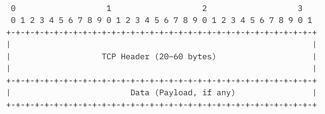
Position:
- The Data field starts at byte offset Data Offset × 4, where Data Offset (bits 96–99) specifies the header length in 32-bit words (5–15, or 20–60 bytes).
- Example: If Data Offset=8, the header is 32 bytes, and the Data field begins at byte 33.
Length:
- Determined implicitly by the total segment length (from the IP header’s Total Length field) minus the TCP header length.
- Formula: Data Length = IP Total Length – IP Header Length – TCP Header Length.
- Constrained by:
- MSS: Negotiated during connection establishment (e.g., 1460 bytes for Ethernet).
- MTU: Network’s maximum packet size (e.g., 1500 bytes for Ethernet).
- Receiver’s Window: Limits the amount of data the receiver can buffer.
Content:
- The Data field contains raw application data, such as text, binary files, or protocol-specific messages (e.g., HTTP, FTP, SMTP).
- TCP treats the payload as an opaque byte stream, with no inherent structure or interpretation, leaving processing to the application layer.
Presence:
- Optional: Many TCP segments (e.g., SYN, ACK, FIN, RST) carry no Data field, serving control purposes only.
- Present in data transfer segments, carrying application content.
Purpose of the Data (Payload) Field
The Data field serves the following primary purposes in TCP communication:
- Transport Application Data:
- Delivers the actual content (e.g., web pages, files, emails) from the sender’s application to the receiver’s application.
- Enable Reliable Delivery:
- Works with TCP’s reliability mechanisms (Sequence Numbers, Acknowledgments, retransmissions) to ensure data is delivered without loss, duplication, or corruption.
- Support Ordered Delivery:
- Uses Sequence Numbers to ensure the payload is reassembled in the correct order, even if segments arrive out of sequence.
- Facilitate Application Communication:
- Provides the data that higher-layer protocols (e.g., HTTP, FTP, SMTP) or applications process, enabling diverse use cases like web browsing, file transfers, or streaming.
- Maximize Network Efficiency:
- Allows transmission of variable-sized payloads within the constraints of MSS and MTU, optimizing throughput while respecting network limits.
Structure and Characteristics
- Variable Length:
- The payload size is not fixed and depends on several factors:
- Maximum Segment Size (MSS): Negotiated during the TCP handshake (via the MSS option), typically 1460 bytes for Ethernet networks (based on a 1500-byte MTU minus 20 bytes for the IP header and 20 bytes for the TCP header).
- Application Data: The amount of data the application provides for transmission.
- Network Constraints: The MTU of the underlying network limits the total segment size (header + payload).
- Example: For an MSS of 1460 bytes, the payload can be up to 1460 bytes, but it may be smaller if the application sends less data or if flow/congestion control limits the segment size.
- The payload size is not fixed and depends on several factors:
- No Payload in Control Segments:
- Certain TCP segments, such as SYN, ACK, FIN, or RST, may have no payload (0 bytes) because they are used for control purposes (e.g., establishing or terminating a connection) rather than data transfer.
- Example: A SYN segment carries only the TCP header (with options like MSS) and no payload.
- Byte-Oriented:
- The payload is treated as a stream of bytes, with its position in the overall data stream identified by the Sequence Number in the TCP header.
- The Sequence Number indicates the byte offset of the first byte in the payload relative to the start of the sender’s byte stream.
- Integrity Protection:
- The payload is included in the Checksum calculation, which covers the TCP header, pseudo-header, and payload. This ensures that any corruption in the payload is detected, and the segment is discarded if the checksum fails.
- No Internal Structure:
- TCP treats the payload as an opaque stream of bytes, with no knowledge of its content or structure. The interpretation of the payload (e.g., as HTML, JSON, or binary data) is handled by the application layer (e.g., HTTP, FTP, SMTP).
Uses of the Data (Payload) Field in TCP Communication
The Data field is primarily used during the data transfer phase of a TCP connection, but its presence and handling vary across connection establishment, data transfer, termination, and error handling. Below are the detailed uses of the Data field in each phase, with examples and explanations of how it interacts with other TCP mechanisms.
1. Connection Establishment (Three-Way Handshake)
- Role: Rarely carries data, as the focus is on synchronization and parameter negotiation.
- Usage:
- SYN, SYN-ACK, ACK Segments: Typically contain no Data field, as they establish the connection by exchanging Initial Sequence Numbers (ISNs), Window sizes, and Options (e.g., MSS, Window Scaling).
- Rare Exception: Some applications (e.g., T/TCP, an experimental extension) may include data in SYN segments to reduce latency, but this is non-standard and uncommon.
- If data is included, it is treated as part of the byte stream, with the Sequence Number indicating its position.
- Example:
- Standard SYN segment:
Client→ Server: SYN=1, Sequence Number=1000, Data Offset=8, Options (MSS=1460, Window Scaling), Data Length=0
- Rare case with data (non-standard):
Client→ Server: SYN=1, Sequence Number=1000, Data Offset=8, Data Length=100 (bytes 1000–1099, e.g., initial application message)- Server → Client: SYN=1, ACK=1, Acknowledgment Number=1100 (acknowledges data)
- Standard SYN segment:
- Significance:
- The Data field is usually absent, keeping the handshake lightweight and focused on control.
- When present, it requires careful handling to ensure reliability, as the receiver must buffer and acknowledge the data.
2. Data Transfer
- Role: Carries the bulk of application data, enabling communication between sender and receiver applications.
- Usage:
- Sender Host:
- Encapsulates application data (e.g., HTTP response, file chunk) into the Data field of TCP segments.
- Assigns a Sequence Number to the first byte of the payload, incrementing it for subsequent segments.
- Limits payload size to the negotiated MSS (e.g., 1460 bytes) to avoid fragmentation and respect the network’s MTU.
- Respects the receiver’s Window (scaled if Window Scaling is enabled) to avoid overwhelming the receiver’s buffer.
- Includes the Data field in the Checksum calculation to ensure integrity.
- Receiver Host:
- Uses the Data Offset to locate the Data field after the header.
- Verifies the Checksum to ensure the payload is uncorrupted; discards the segment if invalid, relying on retransmission.
- Checks the Sequence Number to place the payload in the correct position in the receive buffer, reordering if necessary.
- Sends ACKs with the Acknowledgment Number set to the next expected byte, confirming receipt of contiguous data.
- Uses Selective ACK (SACK) (if enabled) to acknowledge non-contiguous payload blocks, improving retransmission efficiency.
- Delivers the reassembled payload to the application in order, once all prior bytes are received.
- Interaction with Other Fields:
- Sequence Number: Tracks each byte’s position (e.g., a 1000-byte payload with Sequence Number=1001 covers bytes 1001–2000).
- Acknowledgment Number: Confirms receipt (e.g., Acknowledgment Number=2001 confirms bytes 1001–2000).
- Window: Limits the amount of unacknowledged data sent, ensuring flow control.
- Options (e.g., Timestamps, SACK): Enhance performance and reliability during data transfer.
- Sender Host:
- Example:
Sender→ Receiver: Sequence Number=1001, Data Offset=6 (24 bytes), Data Length=1000 (bytes 1001–2000, e.g., HTTP response), Options: [Timestamps]- Receiver: Verifies Checksum, buffers bytes 1001–2000
- Receiver → Sender: ACK=1, Acknowledgment Number=2001, Window=8192, Options: [Timestamps]
- Sender → Receiver: Sequence Number=2001, Data Length=1000 (bytes 2001–3000)
- If a segment is lost:
Sender→ Receiver: Sequence Number=3001, Data Length=1000 (bytes 3001–4000)- Receiver → Sender: ACK=1, Acknowledgment Number=2001, Options: [SACK: 3001–4000]
- Sender: Retransmits bytes 2001–3000.
- Significance:
- The Data field is the primary vehicle for application communication, carrying content like web pages, files, or emails.
- TCP’s reliability (via Sequence Numbers, ACKs, retransmissions) ensures the payload is delivered accurately.
- Flow control (Window) and efficiency (MSS, SACK) optimize payload transmission.
3. Connection Termination (Four-Way Handshake)
- Role: Rarely carries data, as termination focuses on closing the connection.
- Usage:
- FIN and ACK Segments: Typically contain no Data field, as they signal the end of data transmission in one direction.
- Exception: If an application sends final data with a FIN (e.g., closing an HTTP connection with a last response chunk), the Data field carries this payload.
- The Sequence Number tracks the final data bytes, and the receiver acknowledges them before processing the FIN.
- Example:
- Standard FIN segment:
- Client → Server: FIN=1, Sequence Number=5000, Data Offset=5, Data Length=0
- Server → Client: ACK=1, Acknowledgment Number=5001
- FIN with data:
Client→ Server: FIN=1, Sequence Number=5000, Data Length=100 (bytes 5000–5099, e.g., final HTTP chunk)- Server → Client: ACK=1, Acknowledgment Number=5100 (acknowledges data and FIN)
- Standard FIN segment:
- Significance:
- The Data field is minimal or absent, ensuring a lightweight termination process.
- When present, it allows graceful closure with final data delivery, maintaining reliability.
4. Error Handling
- Role: Ensures payload integrity and supports recovery from errors.
- Usage:
- Sender Host:
- Retransmits the Data field of lost segments, identified by duplicate ACKs or timeouts, using the original Sequence Number.
- Uses SACK information (if enabled) to retransmit only missing payload portions.
- Receiver Host:
- Discards segments with invalid Checksums, protecting against corrupted payloads.
- Buffers out-of-order payloads (based on Sequence Numbers) and uses SACK to report received blocks, requesting retransmission of gaps.
- Rejects segments with incorrect Sequence Numbers or those exceeding the Window, preventing erroneous payload processing.
- RST Segments: Typically carry no Data field, as they terminate the connection without transferring payload.
- Sender Host:
- Example:
Sender→ Receiver: Sequence Number=2001, Data Length=1000 (bytes 2001–3000, lost)- Receiver → Sender: ACK=1, Acknowledgment Number=2001 (no progress)
- Sender: Retransmits Sequence Number=2001, Data Length=1000
- Receiver → Sender: ACK=1, Acknowledgment Number=3001
- Significance:
- The Data field’s integrity is protected by the Checksum, ensuring only valid payloads are processed.
- TCP’s error recovery mechanisms (retransmission, SACK) guarantee payload delivery despite network issues.
5. Application-Layer Integration
- Role: Delivers application-specific content to higher-layer protocols or applications.
- Usage:
- The Data field contains protocol-specific messages or raw data for applications, such as:
- HTTP: HTML, JSON, or binary content (e.g., images).
- FTP: File chunks during transfers.
- SMTP: Email headers and body.
- TLS: Encrypted data for secure communication.
- The receiver’s TCP stack strips the header and delivers the payload to the application, which interprets its structure (e.g., HTTP headers, file formats).
- Applications rely on TCP’s reliability to ensure the payload is complete and ordered.
- The Data field contains protocol-specific messages or raw data for applications, such as:
- Example:
- HTTP response:
Sender(Server) → Receiver (Client): Sequence Number=1001, Data Length=1000 (bytes 1001–2000, e.g., HTML: “<html>…</html>”)- Receiver: Delivers payload to browser, which renders the web page.
- HTTP response:
- Significance:
- The Data field bridges the transport layer (TCP) and application layer, enabling diverse use cases.
- TCP’s transparency ensures the payload is delivered unmodified, preserving application semantics.
Additional Uses and Considerations
- Interaction with MSS:
- Mechanism: The MSS, negotiated during connection establishment, caps the Data field’s size to avoid fragmentation.
- Usage: The sender ensures payloads do not exceed the MSS (e.g., 1460 bytes), aligning with the network’s MTU.
- Example: A 3000-byte file is split into two segments (1460 bytes + 1540 bytes), respecting MSS=1460.
- Significance: Optimizes network efficiency by preventing IP fragmentation.
- Flow Control via Window:
- Mechanism: The receiver’s Window field limits the amount of unacknowledged data the sender can transmit, constraining the Data field’s total size across segments.
- Usage: The sender pauses if the Window is exhausted, waiting for ACKs or window updates.
- Example: With Window=8192, the sender sends up to 8192 bytes of payload across multiple segments.
- Significance: Prevents buffer overflow, ensuring reliable payload delivery.
- Checksum for Integrity:
- Mechanism: The Checksum field includes the Data field in its calculation, detecting bit errors.
- Usage: Corrupted payloads are discarded, triggering retransmission.
- Significance: Guarantees the payload’s integrity, critical for application correctness.
- Performance Optimization:
- Mechanism: The Data field’s size is maximized within MSS and Window constraints to reduce header overhead (e.g., one 1460-byte payload vs. multiple smaller ones).
- Usage: Algorithms like Nagle’s (for senders) and delayed ACKs (for receivers) optimize payload transmission by batching data.
- Significance: Improves throughput, especially for large transfers like file downloads.
- Zero-Length Payloads:
- Mechanism: Segments like pure ACKs, SYN, FIN, or RST carry no Data field, serving control purposes.
- Usage: Used for signaling (e.g., ACKs confirm receipt without new data).
- Significance: Reduces overhead when no application data is needed, maintaining efficiency.
Practical Considerations
- No Payload in Control Segments:
- Segments like SYN, FIN, RST, or pure ACKs typically have no payload, as their purpose is connection management or acknowledgment, not data transfer.
- Example: A SYN segment carries only the header (with options like MSS) to negotiate connection parameters.
- Maximum Payload Size:
- The payload size is constrained by the MSS, which is typically 1460 bytes for Ethernet (1500-byte MTU – 20-byte IP header – 20-byte TCP header).
- If options are present (e.g., 12 bytes for Timestamps), the header size increases (e.g., to 32 bytes), reducing the maximum payload to 1500 – 20 – 32 = 1448 bytes.
- Fragmentation:
- If the application data exceeds the MSS, TCP splits it into multiple segments, each with its own payload and Sequence Number.
- Example: A 3000-byte file chunk is sent as two segments: one with a 1460-byte payload and another with a 1540-byte payload (or smaller, depending on MSS).
- Performance Impact:
- Larger payloads maximize throughput by reducing header overhead (e.g., a 1460-byte payload has less overhead than multiple small payloads).
- However, small payloads may be used for interactive applications (e.g., chat) to minimize latency.
- Security:
- The payload is protected by the TCP Checksum, which detects corruption but not malicious tampering. For security, higher-layer protocols like TLS encrypt the payload.
- Attackers may attempt to inject malicious payloads, but TCP’s Sequence Number and Acknowledgment Number mechanisms make such attacks difficult.
- Interaction with Header Fields:
- The payload’s position is determined by the Data Offset (header length).
- Its integrity is verified by the Checksum.
- Its order and delivery are managed by the Sequence Number and Acknowledgment Number.
- Its size is controlled by the Window Size and congestion window.
Example Scenario
Suppose a client downloads a 5000-byte file from a server over TCP, with an MSS of 1460 bytes and no Window Scaling:
- Connection Setup:
- The client sends a SYN segment (no payload, header only) to initiate the connection.
- The server responds with a SYN-ACK (no payload) and advertises an MSS of 1460 bytes.
- The client sends an ACK (no payload) to complete the handshake.
- Data Transfer:
- The server splits the 5000-byte file into four segments:
- Segment 1: Sequence Number 1000, Payload = 1460 bytes (bytes 1000–2459).
- Segment 2: Sequence Number 2460, Payload = 1460 bytes (bytes 2460–3919).
- Segment 3: Sequence Number 3920, Payload = 1460 bytes (bytes 3920–5379).
- Segment 4: Sequence Number 5380, Payload = 620 bytes (bytes 5380–5999).
- The client receives each segment, verifies the Checksum, and sends ACKs with Acknowledgment Numbers 2460, 3920, 5380, and 6000, respectively.
- The server splits the 5000-byte file into four segments:
- Loss Case:
- If Segment 2 (Sequence Number 2460) is lost, the client receives Segment 1 and sends ACK 2460.
- Upon receiving Segment 3 (Sequence Number 3920), the client detects a gap and sends a duplicate ACK for 2460.
- The server retransmits Segment 2, and the client processes all segments, sending ACK 6000 to confirm receipt of the entire file.
- Flow Control:
- If the client’s buffer is limited to 2000 bytes, it advertises a Window Size of 2000 in its ACKs. The server sends only Segments 1 and part of Segment 2 until the client processes data and advertises a larger window.
Practical Examples
- Web Browsing (HTTP):
- Server → Client: Sequence Number=1001, Data Length=1460 (HTML content), MSS=1460, Window=65,536 (scaled).
- Client → Server: ACK=1, Acknowledgment Number=2461, confirming receipt of the HTML payload.
- File Transfer (FTP):
- Sender → Receiver: Sequence Number=2001, Data Length=1460 (file chunk), MSS=1460.
- Receiver → Sender: ACK=1, Acknowledgment Number=3461, Window=8192.
- Multiple segments transfer the file, with payloads reassembled into the original file.
- Streaming (TLS):
- Sender → Receiver: Sequence Number=3001, Data Length=1000 (encrypted video frame).
- Receiver buffers the payload, delivers it to the TLS layer, and sends an ACK.
- Loss Recovery with SACK:
- Sender → Receiver: Sequence Number=2001, Data Length=1000 (lost).
- Sender → Receiver: Sequence Number=3001, Data Length=1000.
- Receiver → Sender: ACK=1, Acknowledgment Number=2001, SACK=3001–4000.
- Sender retransmits the lost payload (2001–3000).
Implementation and Protocol Considerations
- Operating System Role:
- Sender: The TCP stack fragments application data into segments, assigns Sequence Numbers, and ensures payloads respect MSS and Window constraints.
- Receiver: The TCP stack uses Data Offset to locate the payload, verifies the Checksum, and reassembles the byte stream for the application.
- Standards Compliance:
- RFC 9293 defines the Data field as the payload following the header, with length inferred from the IP Total Length and Data Offset.
- RFC 1122 and RFC 793 emphasize reliability and ordering for payload delivery.
- Edge Cases:
- Segments exceeding the MSS or Window are rejected or require retransmission with proper sizing.
- Corrupted payloads (invalid Checksum) are silently discarded, relying on retransmission.
- Validation:
- The receiver ensures the payload aligns with Sequence Numbers, Window, and Checksum, discarding invalid segments.
Summary
The TCP payload is the variable-length data portion of a TCP segment that carries application-layer data, such as web content, files, or messages. Its primary uses include:
- Transporting application data reliably across the network.
- Supporting reliable delivery through checksums, retransmissions, and acknowledgments.
- Enabling ordered delivery using sequence numbers.
- Facilitating flow control by respecting the receiver’s buffer capacity.
- Supporting congestion control by aligning with the sender’s congestion window.
- Carrying higher-layer protocol data (e.g., HTTP, SMTP, TLS).
- Handling urgent data (rarely used) when marked by the URG flag.
By serving as the container for user data, the TCP payload is the core of TCP’s data transfer functionality, leveraging the protocol’s robust mechanisms to ensure reliable, ordered, and error-free delivery in diverse network environments.
Use of the Options field in the TCP such as Maximum Segment Size (MSS), Window Scaling, and Selective ACK (SACK)
The TCP (Transmission Control Protocol) header fields—Window, Flags, and Options, along with Sequence Number and Acknowledgment Number—play critical roles in establishing and managing reliable data communication. During connection establishment, these fields are used to negotiate key parameters such as the Maximum Segment Size (MSS), Window Scaling, and Selective ACK (SACK) support. In data communication, these fields, along with the negotiated parameters, ensure efficient, reliable, and ordered data transfer between the sender and receiver hosts. Below, I provide a detailed explanation of how these fields and parameters are used during connection establishment and data communication, as specified in RFC 9293 (August 2022) and related RFCs (e.g., RFC 7323, RFC 2018).
1. Connection Establishment: Negotiating MSS, Window Scaling, and SACK
The TCP connection establishment phase, known as the three-way handshake, involves the exchange of SYN, SYN-ACK, and ACK segments to synchronize sequence numbers, establish flow control, and negotiate optional parameters. The Window, Flags, and Options fields are central to negotiating MSS, Window Scaling, and SACK support.
Overview of the Three-Way Handshake
- Participants: Sender Host (e.g., Client) and Receiver Host (e.g., Server).
- Segments Exchanged:
- Client → Server: SYN (Synchronize) segment.
- Server → Client: SYN-ACK (Synchronize-Acknowledge) segment.
- Client → Server: ACK (Acknowledge) segment.
- Objective: Synchronize Sequence Numbers, agree on connection parameters (MSS, Window Scaling, SACK), and establish initial flow control via the Window field.
Role of TCP Header Fields in Negotiation
Flags
- Location: Bits 104–111 in the TCP header (fifth 32-bit word).
- Relevant Flags:
- SYN (Synchronize): Set to 1 in SYN and SYN-ACK segments to initiate connection establishment.
- ACK (Acknowledge): Set to 1 in SYN-ACK and ACK segments to acknowledge receipt of the SYN.
- Usage in Connection Establishment:
- SYN=1: Indicates a connection request, carrying the Initial Sequence Number (ISN) and options for negotiation (MSS, Window Scaling, SACK-Permitted).
- ACK=1: Confirms receipt of the SYN, carrying the Acknowledgment Number to acknowledge the sender’s ISN.
- Example:
- Client SYN: SYN=1, ACK=0 (no acknowledgment yet).
- Server SYN-ACK: SYN=1, ACK=1 (acknowledges client’s ISN).
- Client ACK: SYN=0, ACK=1 (acknowledges server’s ISN).
- Significance: Flags drive the handshake process, enabling negotiation and synchronization.
Window
- Location: Bits 112–127 (16 bits) in the TCP header.
- Purpose: Advertises the receiver’s buffer capacity (receive window) in bytes, starting from the Acknowledgment Number.
- Usage in Connection Establishment:
- In SYN-ACK and ACK segments (with ACK=1), the Window field specifies the initial buffer size the receiver can accept.
- The Window value is unscaled in SYN segments but may be interpreted with the Window Scaling option (negotiated via Options) for larger effective windows.
- Example:
- Server SYN-ACK: Window=8192 (indicating 8192 bytes available).
- Client ACK: Window=16384 (indicating 16384 bytes available).
- Significance: Establishes initial flow control, ensuring the sender does not overwhelm the receiver’s buffer. Window Scaling enhances this for high-bandwidth networks.
Options
- Location: Variable-length field after the fixed 20-byte header, up to 40 bytes.
- Purpose: Negotiates optional parameters like MSS, Window Scaling, and SACK-Permitted.
- Usage in Connection Establishment:
- The Options field in SYN and SYN-ACK segments includes Type-Length-Value (TLV) structures to propose and agree on parameters.
- Common options for negotiation:
- Maximum Segment Size (MSS) (Kind=2, Length=4):
- Specifies the maximum size of the TCP data payload (excluding TCP/IP headers) the sender can receive.
- Helps avoid fragmentation by aligning with the network’s Maximum Transmission Unit (MTU).
- Example: MSS=1460 (for Ethernet MTU=1500, accounting for 20-byte IP header + 20-byte TCP header).
- Format: [Kind=2, Length=4, MSS Value (2 bytes)].
- Window Scaling (Kind=3, Length=3):
- Proposes a shift factor (0–14) to scale the Window field, supporting larger receive windows (up to 1 GB).
- Both endpoints must agree on scaling in SYN and SYN-ACK for it to be used.
- Example: Shift=7 (scale factor = 2⁷ = 128).
- Format: [Kind=3, Length=3, Shift Count (1 byte)].
- SACK-Permitted (Kind=4, Length=2):
- Indicates support for Selective Acknowledgments, allowing acknowledgment of non-contiguous data blocks during data transfer.
- Must be included in both SYN and SYN-ACK to enable SACK.
- Format: [Kind=4, Length=2].
- Timestamps (Kind=8, Length=10, optional in this context):
- Often included to support Round-Trip Time (RTT) estimation and Protection Against Wrapped Sequences (PAWS).
- Format: [Kind=8, Length=10, TS Value (4 bytes), TS Echo Reply (4 bytes)].
- No-Operation (NOP) (Kind=1, Length=1):
- Used for padding to align options to 32-bit boundaries.
- Maximum Segment Size (MSS) (Kind=2, Length=4):
- Negotiation Process:
- Client SYN: Includes MSS, Window Scaling, SACK-Permitted, and optionally Timestamps.
- Server SYN-ACK: Responds with its own MSS, agrees to Window Scaling (specifying its shift factor), confirms SACK-Permitted, and includes Timestamps if supported.
- Client ACK: Typically includes minimal options (e.g., Timestamps if negotiated), as most parameters are finalized.
- If an endpoint does not support an option (e.g., Window Scaling), it omits it in its response, and the option is not used.
- Data Offset: Set to reflect the header length, including options (e.g., Data Offset=8 for a 32-byte header with 12 bytes of options).
- Example:
Client→ Server: SYN=1, Sequence Number=1000, ACK=0, Data Offset=8 (32 bytes), Window=16384,- Options:
- [Kind=2, Length=4, MSS=1460]
- [Kind=3, Length=3, Shift=7]
- [Kind=4, Length=2]
- [Kind=8, Length=10, TS Value=123456, TS Echo=0]
- [Kind=1] (NOP)
- Options:
- Server → Client: SYN=1, ACK=1, Sequence Number=2000, Acknowledgment Number=1001, Data Offset=8, Window=8192,
- Options:
- [Kind=2, Length=4, MSS=1460]
- [Kind=3, Length=3, Shift=7]
- [Kind=4, Length=2]
- [Kind=8, Length=10, TS Value=789012, TS Echo=123456]
- [Kind=1] (NOP)
- Options:
- Client → Server: ACK=1, Sequence Number=1001, Acknowledgment Number=2001, Data Offset=6 (24 bytes), Window=16384,
- Options:
- [Kind=8, Length=10, TS Value=123500, TS Echo=789012]
- [Kind=1] [Kind=1] (NOPs)
- Options:
- Significance:
- MSS: Ensures segments fit within the network’s MTU, reducing fragmentation and improving efficiency.
- Window Scaling: Enables large receive windows for high-bandwidth, high-latency networks, maximizing throughput.
- SACK-Permitted: Sets the stage for efficient error recovery during data transfer by allowing selective acknowledgments.
- Flags and Window: Synchronize the connection and establish initial flow control, critical for reliable communication.
Rules and Considerations
- MSS:
- Typically derived from the network’s Maximum Transmission Unit (MTU) minus TCP/IP header overhead (e.g., MTU=1500 → MSS=1500 – 40 = 1460 for IPv4).
- If no MSS is specified, a default of 536 bytes is assumed (per RFC 1122).
- The receiver must respect the sender’s MSS to avoid fragmentation.
- Window Scaling:
- Only enabled if both endpoints include the option in SYN and SYN-ACK.
- The shift count is applied to the Window field in all segments, but the Window field itself remains unscaled (16 bits).
- If one endpoint does not support Window Scaling, the unscaled Window field (max 65,535 bytes) is used.
- SACK-Permitted:
- Must be included in both SYN and SYN-ACK to enable SACK.
- If either endpoint omits SACK-Permitted, SACK is disabled, and only cumulative ACKs are used.
- Data Offset:
- Set to reflect the header length, including options (e.g., Data Offset=8 for a 32-byte header with 12 bytes of options).
- Ensures the receiver correctly parses the Options field and locates the data payload.
- Backward Compatibility:
- Unrecognized options are ignored, ensuring older TCP stacks process segments without errors.
- Example: A legacy server ignoring Window Scaling uses the unscaled Window field.
2. Data Communication: Using Sequence Number, Acknowledgment Number, Window, MSS, Window Scaling, and SACK
Once the connection is established, the Sequence Number, Acknowledgment Number, Window, and negotiated parameters (MSS, Window Scaling, SACK) are used to manage reliable, ordered, and efficient data transfer between the Sender Host and Receiver Host. These fields and parameters work together to track data, confirm receipt, control flow, and recover from errors.
Overview of Data Communication
- Participants: Sender Host (sends data segments) and Receiver Host (receives data, sends ACKs).
- Objective: Transfer application data (e.g., HTTP responses, file transfers) reliably, ensuring no loss, duplication, or reordering, while optimizing performance.
- Mechanisms:
- Sequence Number: Tracks the position of each byte in the sender’s data stream.
- Acknowledgment Number: Confirms receipt of contiguous bytes, indicating the next expected byte.
- Window: Regulates the amount of data the sender can transmit based on the receiver’s buffer capacity.
- MSS: Limits segment size to avoid fragmentation.
- Window Scaling: Scales the Window field for larger buffers in high-speed networks.
- SACK: Enhances error recovery by acknowledging non-contiguous data.
Role of Each Field and Parameter
Sequence Number
- Location: Bits 32–63 (32 bits) in the TCP header.
- Purpose: Identifies the position of the first byte of data in a segment relative to the Initial Sequence Number (ISN).
- Usage by Sender Host:
- Assigns a Sequence Number to each segment, incrementing it by the number of data bytes sent.
- Tracks sent bytes to manage retransmissions if segments are lost.
- Example: For a segment with 1000 bytes, Sequence Number=1001 → next segment’s Sequence Number=2001.
- Usage by Receiver Host:
- Uses Sequence Numbers to reorder segments if they arrive out of order.
- Detects missing segments (gaps in Sequence Numbers) or duplicates (repeated Sequence Numbers).
- Buffers out-of-order segments until gaps are filled, then delivers data to the application in order.
- Example:
- Sender → Receiver: Sequence Number=1001, Data Length=1000 (bytes 1001–2000)
- Receiver: Checks Sequence Number; if 1001 is expected, processes data.
- Significance: Ensures ordered delivery and loss detection, critical for reliability.
Acknowledgment Number
- Location: Bits 64–95 (32 bits) in the TCP header.
- Purpose: Specifies the next byte the receiver expects, confirming receipt of all prior contiguous bytes (when ACK=1).
- Usage by Sender Host:
- Monitors Acknowledgment Numbers in received ACKs to confirm which bytes were successfully received.
- Advances the send window based on the Acknowledgment Number, allowing transmission of new data.
- Triggers retransmission if duplicate ACKs (same Acknowledgment Number) indicate loss or if no ACK is received within a timeout.
- Usage by Receiver Host:
- Sets the Acknowledgment Number in ACK segments to the next expected byte, reflecting the highest contiguous byte received.
- Sends duplicate ACKs if segments are missing, signaling loss to the sender.
- Example:
Receiver→ Sender: ACK=1, Acknowledgment Number=2001 (confirms bytes 1001–2000)- Sender: Advances send window to send bytes starting from 2001.
- Significance: Drives reliable delivery by confirming receipt and identifying losses.
Window
- Location: Bits 112–127 (16 bits) in the TCP header.
- Purpose: Advertises the receiver’s available buffer space (receive window) in bytes, starting from the Acknowledgment Number.
- Usage by Sender Host:
- Limits transmission to the receiver’s advertised Window size (scaled if Window Scaling is enabled), ensuring the receiver’s buffer is not overwhelmed.
- Pauses transmission if the Window is 0 (zero window), resuming when a window update (non-zero Window) is received.
- Adjusts the send window dynamically based on Window updates in ACKs.
- Usage by Receiver Host:
- Sets the Window field in ACK segments based on current buffer availability, updated as the application reads data.
- Advertises a zero window if the buffer is full, halting sender transmission until space is freed.
- Sends window updates (ACKs with larger Window values) to resume transmission.
- Example:
Receiver→ Sender: ACK=1, Acknowledgment Number=2001, Window=8192- Sender: Sends up to 8192 bytes (e.g., bytes 2001–10192).
- Receiver → Sender: ACK=1, Acknowledgment Number=4001, Window=6192 (buffer reduced)
- Significance: Implements flow control, balancing sender throughput with receiver capacity.
Maximum Segment Size (MSS)
- Negotiated: In SYN and SYN-ACK segments via the Options field (Kind=2, Length=4).
- Purpose: Defines the maximum size of the TCP data payload (excluding TCP/IP headers) each host can receive, typically based on the network’s MTU.
Sender’s Role:
- Action:
- The sender ensures that the data payload in each segment does not exceed the receiver’s MSS.
- The sender constructs segments by combining the TCP header (20 bytes + options), IP header (20 bytes for IPv4), and data payload up to the MSS.
- Example:
- Client sending to server (server MSS=1440):
- Segment: Sequence Number=1001, Data Length=1440 bytes, Header=24 bytes (with Timestamps).
- Total packet size = 20 (IP) + 24 (TCP) + 1440 (data) = 1484 bytes, fitting within a typical Ethernet MTU (1500).
- The client avoids sending larger payloads (e.g., 1500 bytes), which would require fragmentation.
- Client sending to server (server MSS=1440):
- Behavior:
- If the application provides more data than the MSS, the sender splits it into multiple segments, each respecting the MSS.
- Example: 3000 bytes of data → two segments (1440 + 1560 bytes, adjusted to 1440 + 1440 if needed).
- Significance:
- Prevents fragmentation at the IP layer, reducing overhead and improving efficiency.
- Aligns with network MTU, minimizing packet loss or reassembly delays.
Receiver’s Role:
- Action:
- The receiver accepts segments up to its advertised MSS without requiring fragmentation.
- If a segment exceeds the MSS (e.g., due to sender error), the receiver may discard it or rely on IP reassembly, though this is rare due to sender compliance.
- Example:
- Server receiving from client (server MSS=1440):
- Accepts segments with payloads up to 1440 bytes, processes them, and delivers data to the application.
- Server receiving from client (server MSS=1440):
- Behavior:
- The receiver’s TCP stack buffers incoming data and acknowledges it, unaffected by MSS during receipt (as MSS governs sending).
- Significance:
- Ensures the receiver’s network interface can handle incoming packets without fragmentation.
- Simplifies data processing by aligning with negotiated parameters.
Window Scaling
- Negotiated: In SYN and SYN-ACK segments via the Options field (Kind=3, Length=3). Both endpoints agree on a shift count (e.g., shift=7, scale factor = 128). The Window field value is multiplied by 2^shift internally.
- Purpose: Scales the 16-bit Window field by a shift factor (2ⁿ, n=0–14), supporting larger receive windows (up to 1 GB) for high-bandwidth, high-latency networks.
Sender’s Role:
- Action:
- The sender interprets the receiver’s Window field in ACK segments as a scaled value: Scaled Window = Window × 2^shift.
- The sender transmits data within the scaled window, starting from the Acknowledgment Number, without exceeding the receiver’s buffer capacity.
- The sender’s send window is the minimum of the receiver’s scaled window (flow control) and the sender’s congestion window (congestion control).
- Example:
- Receiver sends: ACK=1, Acknowledgment Number=2001, Window=512, Shift=7.
- Scaled Window = 512 × 128 = 65,536 bytes.
- Sender can transmit bytes 2001–67,536 (up to 65,536 bytes) before needing another ACK.
- Sender sends multiple segments (e.g., 1440 bytes each) within this window.
- Behavior:
- As ACKs arrive, the sender slides its send window forward, using the updated Acknowledgment Number and scaled Window.
- If the receiver advertises a zero window (scaled to 0), the sender pauses and uses zero window probing.
- Significance:
- Enables full utilization of high-speed, high-latency links by allowing large bursts of data.
- Prevents buffer overflow by respecting the receiver’s capacity.
Receiver’s Role:
- Action:
- The receiver advertises its available buffer space in the Window field, scaled down by the shift count: Window = Actual Buffer ÷ 2^shift.
- The receiver updates the Window field in each ACK segment based on buffer availability, reflecting data read by the application.
- Example:
- Receiver’s buffer = 131,072 bytes, Shift=7 (scale=128).
- Advertised Window = 131,072 ÷ 128 = 1024.
- Sends: ACK=1, Acknowledgment Number=2001, Window=1024 (scaled to 131,072 bytes).
- Behavior:
- As the application reads data, the receiver increases the Window, sending window updates (ACKs with larger Window values).
- If the buffer fills, the receiver advertises a smaller or zero window, pausing the sender.
- Significance:
- Dynamically controls the sender’s rate, preventing buffer overflow.
- Supports high-throughput connections by advertising large windows.
- Example:
- Negotiated shift=7 (scale factor=128) in SYN exchange.
- Receiver → Sender: Window=512 → Scaled Window = 512 × 128 = 65,536 bytes.
- Sender transmits up to 65,536 bytes starting from the Acknowledgment Number.
- Significance: Enables TCP to utilize high-speed networks fully, critical for large file transfers or streaming.
Selective ACK (SACK)
- Negotiated: In SYN and SYN-ACK segments via the SACK-Permitted option (Kind=4, Length=2).
- Purpose: Allows the receiver to acknowledge non-contiguous data blocks, improving retransmission efficiency in lossy networks.
- Usage by Sender Host:
- Processes SACK options (Kind=5, Length=10–34) in ACKs to identify which non-contiguous blocks were received.
- Retransmits only missing segments, avoiding unnecessary retransmissions of already-received data.
- Usage by Receiver Host:
- Includes SACK options in ACK segments when non-contiguous data is received, specifying up to four blocks of received bytes.
- Continues sending cumulative ACKs (via Acknowledgment Number) for contiguous data, supplemented by SACK for gaps.
- Example:
- Sender → Receiver: Sequence Number=1001, Data Length=1000 (bytes 1001–2000)
- Sender → Receiver: Sequence Number=2001, Data Length=1000 (bytes 2001–3000, lost)
- Sender → Receiver: Sequence Number=3001, Data Length=1000 (bytes 3001–4000)
- Receiver → Sender: ACK=1, Acknowledgment Number=2001, Window=8192,
- Options:
- [Kind=5, Length=10, Block 1=3001–4000]
- Sender: Retransmits bytes 2001–3000.
- Receiver → Sender: ACK=1, Acknowledgment Number=4001 (all data received).
- Significance: Enhances efficiency in lossy networks by minimizing retransmission overhead.
Integrated Example of Data Communication
- Setup: Connection established with:
- Client ISN=1000, Server ISN=2000.
- MSS=1460, Window Scaling shift=7 (scale factor=128), SACK-Permitted enabled.
- Data Transfer:
- Sender (Client) → Receiver (Server):
- Segment 1: Sequence Number=1001, Data Length=1460 (bytes 1001–2460), Options: [Timestamps].
- Segment 2: Sequence Number=2461, Data Length=1460 (bytes 2461–3920, lost).
- Segment 3: Sequence Number=3921, Data Length=1460 (bytes 3921–5380).
- Receiver (Server) → Sender (Client):
- ACK: ACK=1, Acknowledgment Number=2461 (confirms bytes 1001–2460), Window=512 (Scaled Window=512 × 128=65,536 bytes), Options:
- [Timestamps]
- [SACK: Block 1=3921–5380] (acknowledges non-contiguous data).
- ACK: ACK=1, Acknowledgment Number=2461 (confirms bytes 1001–2460), Window=512 (Scaled Window=512 × 128=65,536 bytes), Options:
- Sender (Client):
- Sees duplicate ACK with Acknowledgment Number=2461 and SACK block=3921–5380.
- Retransmits Segment 2: Sequence Number=2461, Data Length=1460 (bytes 2461–3920).
- Receiver (Server) → Sender (Client):
- ACK: ACK=1, Acknowledgment Number=5381 (confirms all bytes 1001–5380), Window=512 (65,536 bytes), Options: [Timestamps].
- Sender (Client):
- Advances send window to send new data (e.g., bytes 5381–6840, respecting MSS=1460 and scaled Window=65,536).
- Sender (Client) → Receiver (Server):